

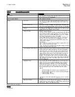


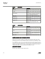


Item
Description
Backup Pwr Failure
Indicates the absence of Backup Power circuiting
when Backup Power option has been detected.
Low Current Block
When enabled the control determines if Load Current
following a tap change is less than 4 mA, coincident
with Tap Delta Voltage being less than 4 Vac. When
these conditions exist the control will initiate an alarm
and block regulation.
Individual Tap Wear
The number of operations on any single tap exceeds
the Individual Tap Wear Alarm setting.
Tap Changer Failure
When the Operation Counter Configuration is set to
"Cam Follower" and this alarm has been enabled,
indicates the counter contact input has detected a
Tap Changer Failure condition.
A Cam Follower contact is a cam driven contact
which is normally closed when the Tapchanger is at
rest, and opens and closes once during each tap
operation in either direction. If this contact does not
open and close within 30 seconds after the control
issues a Raise or Lower in either local automatic or
remote manual operational modes, this alarm will
activate. This alarm can be reset either by the Cam
Follower contact operating correctly during a
subsequent Raise or Lower operation, or if reset by
the user.
LDC/LDZ
Any value other than zero has been set for LDC/LDZ.
Line Current Limit
The line current is exceeding the respective
maximum current limit setting and the alarm output is
on due to this condition.
Reverse Power
Reverse power is present at the control and the
alarm output is on due to this condition.
Abnormal Tap Position
Abnormal Tap Position is indicated when the alarm is
enabled, KeepTrack
TN
is enabled and the neutral
input is detected but the present tap position at that
instant is neither at minus one nor plus one. The
Abnormal Tap Position Alarm will also be activated
when the Motor Seal-in Failure detection feature has
detected a Motor Seal-in Failure.
Voltage Reduction
Any level of voltage reduction is active.
VAr Bias Lead or Lag
Indicates when the VAr Bias effect (Lead or Lag) has
exceeded the time limit imposed by the Max VAr Bias
Duration Setting.
Table continues on next page
1VAC388793-MB A
Section 4
TCC600
TCC300
157
User Manual
Summary of Contents for TCC300
Page 1: ...Digital Tapchanger Control TCC300 User Manual ...
Page 2: ......
Page 3: ...Document ID 1VAC388793 MB Issued 2016 08 10 Revision A Copyright 2016 ABB All rights reserved ...
Page 26: ...20 ...
Page 34: ...28 ...
Page 91: ...1VAC388793 MB A Section 3 Operation TCC300 85 User Manual ...
Page 126: ...120 ...
Page 176: ...Section 4 1VAC388793 MB A TCC600 170 TCC300 User Manual ...
Page 260: ...254 ...
Page 328: ...322 ...
Page 494: ...488 ...
Page 556: ...550 ...
Page 580: ...574 ...
Page 600: ...594 ...
Page 700: ...694 ...
Page 710: ...704 ...
Page 712: ...706 ...
Page 713: ...707 ...
Page 714: ......
Page 715: ......