


COMMUNICATION
CNFG UTIL
UTILITIES
COMM MNTR
MONITOR
UTIL SETP
SETPOINTS
MNTR CNFG
CONFIGURATION
SETP COMM
Press ENT to view
Tapchanger Status
Press ENT to view
Alarm Status
Press ENT to view
Input Status
Press ENT to view
Output Status
Peak RMS Curr
x.x mA (x.x) T
Avg RMS Curr
x.x mA (xx.x) T
Profile Duration
xxx.x ms(xxx.x) T
Peak Motor Current E
x.x mA
Voltage % THD
x.x %
Current % THD
xx.x %
Press ENT to view
Voltage Harmonics
Press ENT to view
Current Harmonic
Status
Motor Current
Harmonics
Tap Information
Present Demand
Demand History
Energy Metering
Tap Position/Cal
DISABLE
Drag Hands E
L= 0 N R= 0 N
Definite Timer
Raise xxs Lower xxs
Intertap Timer
x %
Operation Counter
0
Resettable Counter E
0
Neutral Sw Counter
x
Lower Counter
x
Raise Counter
x
Press ENT to view
specific Tap Stats
Press ENT to clear
Tap Statistics
RTN Success Counter
00000
RTN Status
DISABLED
Count to RTN Active
00000
Demand Interval
xx Min
Demand Load Voltage
xxx.x Volts
Demand Pri. Current
xxx.x Amps
Demand Pri. Watts
x.xx MW
Demand Pri. VArs
x.xx MVArs
Demand Pri. VA
x.xx MVA
Demand Interval
xx Min
Min Load Voltage E
x.x Volts
Max Load Voltage E
xxx.x Volts
Max Pri.Current
E
xxx.x Amps
Max Primary Watts E
x.xx MW
Max Primary VArs
E
x.xx MVAr
Max Primary VA
E
x.xx MVA
PF @ Max VA
E
x.xxx PF
Press ENT to reset
Demand History
Press ENT to perform
Master Reset
Watt Hours Fwd
E
x kWh
Lagging VAr Hours E
x kVArh
Watt Hours Rev
E
xx kWh
Leading VAr Hours E
xx kVArh
Press ENT to reset
Energy Metering
Press ENT to perform
Master Reset
If DVAr enabled
Metering
Load Voltage
xxx.x Volts
Meter Out Voltage
xxx.x Volts
Source Voltage
Disabled
Load Current
x.x mA LEAD/LAG
Circulating Current
x.x mA LEAD/LAG
DVar Current
x.x mA LEAD/LAG
Compensated Voltage
xxx.x Volts
Primary Voltage
x.xx kV
Primary Src Voltage
Disabled
Primary Current
xxx.x Amps
Primary Watts
x.xx MW
Primary VArs
x.xx MVArs
Primary VA
x.xx MVA
Power Factor
x.xxx LEAD/LAG
Frequency
xx.x Hz
Load Voltage
xxx.x Volts
Watt Hours Fwd
E
x kWh
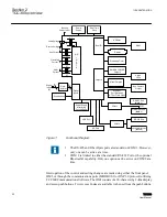
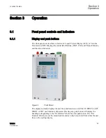
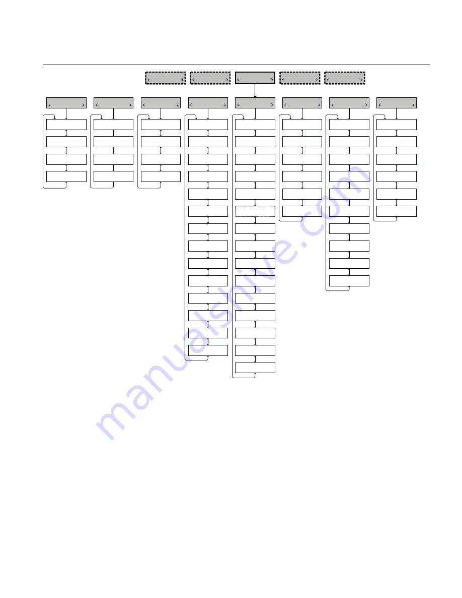
GUID-51E8890C-FA2F-4A04-99BE-424E46278EF8 V1 EN
Figure 4:
Example of HMI Menu Structure, Header, Sub-Header and Data/Data Entry Menus
From the sub-header level, the user can navigate to the adjacent sub-headers with the
LEFT and RIGHT push buttons, return to the header level by pressing the EXIT or UP
push buttons, or enter the data/data entry level by pressing ENT or DOWN. Once in the
data/data entry screens, the user can navigate through the list with the UP and DOWN push
buttons. In this level the list wraps around. To exit the level, the user can press EXIT to
return to the corresponding sub-header, or use the LEFT and RIGHT push buttons to go
to the adjacent sub-header level. To enter data, reset parameters or access data screens,
press ENT.
1VAC388793-MB A
Section 3
Operation
TCC300
31
User Manual
Summary of Contents for TCC300
Page 1: ...Digital Tapchanger Control TCC300 User Manual ...
Page 2: ......
Page 3: ...Document ID 1VAC388793 MB Issued 2016 08 10 Revision A Copyright 2016 ABB All rights reserved ...
Page 26: ...20 ...
Page 34: ...28 ...
Page 91: ...1VAC388793 MB A Section 3 Operation TCC300 85 User Manual ...
Page 126: ...120 ...
Page 176: ...Section 4 1VAC388793 MB A TCC600 170 TCC300 User Manual ...
Page 260: ...254 ...
Page 328: ...322 ...
Page 494: ...488 ...
Page 556: ...550 ...
Page 580: ...574 ...
Page 600: ...594 ...
Page 700: ...694 ...
Page 710: ...704 ...
Page 712: ...706 ...
Page 713: ...707 ...
Page 714: ......
Page 715: ......