


Power
Supply
Load Voltage
Line Current
VT
CT
A/D
I
N
P
U
T
S
Digital
Inputs
Pushbuttons
Opto-
Isolator
9
9
Digital
Inputs
(9)
Real-Time
Clock
Power Supply
Monitoring
Circuits/Reset
USB Port
COM 1
Fiber Optic Port
(
Note 1
)
RS-485 Port
(
Note 1
)
COM 2
SD Card
Ethernet
Port (Optional)
UTP or Fiber Optic
Outputs
Alarm Outputs
RAISE & LOWER
Outputs
Status
LEDs
Bus I/O
Display
EPROM
RAM
Watchdog Timer
OR
Source Voltage
Aux Contact
Output
Optional Bluetooth
(
Note 2
)
RS-232 Port
Backup
Power Input
Motor
Current
CT
Circulating
Current
CT
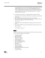
GUID-F8B673A3-CE7F-4037-9A3F-3B2188F648F2 V1 EN
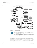
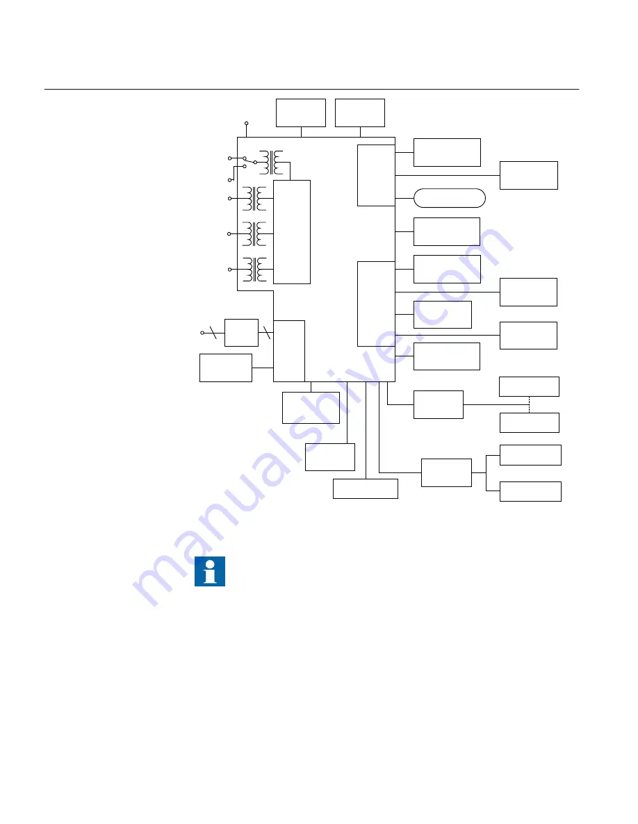
Figure 1:
Functional Diagram
1. The RS-485 and Fiber Optic ports are standard on COM 1. However,
only one can be active at a time.
2. COM 2 is limited to either the standard RS-232 Port or the optional
Bluetooth® capability. Only one option can be active on COM 2 at a
time.
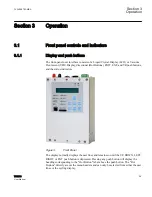
Interrogation of the control and setting changes are made using either the front panel
HMI, or through the communications ports (MODBUS® or DNP3.0 protocol) utilizing
TCC600 Communications Software. The HMI consists of a 20-character by 2
‑
line display
and seven push buttons. Two Access Codes are available to the user from the push buttons.
Section 2
1VAC388793-MB A
TCC300 overview
22
TCC300
User Manual
Summary of Contents for TCC300
Page 1: ...Digital Tapchanger Control TCC300 User Manual ...
Page 2: ......
Page 3: ...Document ID 1VAC388793 MB Issued 2016 08 10 Revision A Copyright 2016 ABB All rights reserved ...
Page 26: ...20 ...
Page 34: ...28 ...
Page 91: ...1VAC388793 MB A Section 3 Operation TCC300 85 User Manual ...
Page 126: ...120 ...
Page 176: ...Section 4 1VAC388793 MB A TCC600 170 TCC300 User Manual ...
Page 260: ...254 ...
Page 328: ...322 ...
Page 494: ...488 ...
Page 556: ...550 ...
Page 580: ...574 ...
Page 600: ...594 ...
Page 700: ...694 ...
Page 710: ...704 ...
Page 712: ...706 ...
Page 713: ...707 ...
Page 714: ......
Page 715: ......