


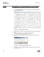

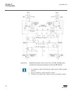


TRANS 2
TRANS 1
Source
LOADS
LOADS
LOADS
LOADS
52-2
6
5
V
T
8
L
L
R
R
1
3
7
9
52-1
52-3
2
1
4
3
5.0 A
0.2 A
Main CT
M-0169A Auxiliary
Current Transformer
90 Relay
Main VT
Motor
Power In
Motor
Auxiliary
Relay Coils
I
P
4
2
I
L
PAR
Disable
52-3b
43P
6
5
V
T
8
L
L
R
R
1
3
7
9
2
1
4
3
5.0 A
0.2 A
Main CT
M-0169A Auxiliary
Current Transformer
90 Relay
Main VT
Motor
Power In
Motor
Auxiliary
Relay Coils
I
P
4
2
I
L
PAR
Disable
52-3b
43P
Optional
52-2b
52-1b
Optional
52-2b
52-1b
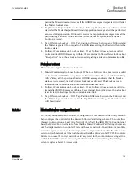
GUID-0CCD991A-A496-468E-BF35-526F1AD9D910 V1 EN
Figure 332:
ΔVAR
®
2 Paralleling
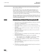
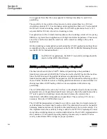
Paralleling by the ΔVAR2 method does not use the M
‑
0115A Parallel Balancing Module.
This method of paralleling can only be used for two transformers. See
ΔVAR2 connections. Instead, the two load currents are brought into the control, and the
actual ΔVAR's which exist between the paralleled transformers is calculated internally.
When using the ΔVAR2 method, the control's load current input is to be connected to the
load current CT of the transformer which is controlling the tap position. The control's
circulating current is to be connected to the load current CT for the opposite paralleled
transformer.
Section 6
1VAC388793-MB A
Configuration
406
TCC300
User Manual
Summary of Contents for TCC300
Page 1: ...Digital Tapchanger Control TCC300 User Manual ...
Page 2: ......
Page 3: ...Document ID 1VAC388793 MB Issued 2016 08 10 Revision A Copyright 2016 ABB All rights reserved ...
Page 26: ...20 ...
Page 34: ...28 ...
Page 91: ...1VAC388793 MB A Section 3 Operation TCC300 85 User Manual ...
Page 126: ...120 ...
Page 176: ...Section 4 1VAC388793 MB A TCC600 170 TCC300 User Manual ...
Page 260: ...254 ...
Page 328: ...322 ...
Page 494: ...488 ...
Page 556: ...550 ...
Page 580: ...574 ...
Page 600: ...594 ...
Page 700: ...694 ...
Page 710: ...704 ...
Page 712: ...706 ...
Page 713: ...707 ...
Page 714: ......
Page 715: ......