


V
S
S
L
SL
Regulator
Bypass
Arrestor
I
PRI
Source
Voltage
I
L
0.2 A
Nominal
Load Current
Main CT
Primary
Current
V
PRI
Primary
Voltage
120 V
Nominal
VT
V
LOC
Compensated
Voltage
V
COMP
Theoretical
Load Center
Transmission/
Distribution Line
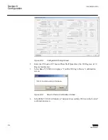
NOTE
: The VT and CT are usually integral to the regulator.
Indicates calculated quantities
GUID-A89B422C-1E9B-4D1B-88FD-E533FF66A54F V1 EN
Figure 305:
Secondary Quantity Metering and Primary Quantity Calculations for
Regulator Applications
I
PRI
0.2 A
Nominal
Load Current
Main CT
Primary
Current
V
PRI
Primary
Voltage
120 V
Nominal
VT
V
LOC
Compensated
Voltage
V
COMP
Theoretical
Load Center
Transmission/
Distribution Line
Indicates calculated quantities
I
L
Auxiliary
CT
Transformer
High
Voltage
Low
Voltage
NOTE
: The figure shows a Line-to-Ground VT and a
single-phase CT. The system can also accommodate a
Line-to-Line VT and a Phase-to-Phase connected CT.
GUID-A3C2F09C-5B01-4938-AA65-3C56CF85FD08 V1 EN
Figure 306:
Secondary Quantity Metering and Primary Quantity Calculations for
Transformer Applications
Section 6
1VAC388793-MB A
Configuration
374
TCC300
User Manual
Summary of Contents for TCC300
Page 1: ...Digital Tapchanger Control TCC300 User Manual ...
Page 2: ......
Page 3: ...Document ID 1VAC388793 MB Issued 2016 08 10 Revision A Copyright 2016 ABB All rights reserved ...
Page 26: ...20 ...
Page 34: ...28 ...
Page 91: ...1VAC388793 MB A Section 3 Operation TCC300 85 User Manual ...
Page 126: ...120 ...
Page 176: ...Section 4 1VAC388793 MB A TCC600 170 TCC300 User Manual ...
Page 260: ...254 ...
Page 328: ...322 ...
Page 494: ...488 ...
Page 556: ...550 ...
Page 580: ...574 ...
Page 600: ...594 ...
Page 700: ...694 ...
Page 710: ...704 ...
Page 712: ...706 ...
Page 713: ...707 ...
Page 714: ......
Page 715: ......