


T
X
In-Line, 6-Pin
Connector for the
M-2025B(D)
Current Loop Module
24-Pin Blue Connector
for M-2000 Series
Adapter Panels or
direct connection
Bottom View
Top View
Source Voltage Input
One Aux Output
Three Aux Inputs
Front
Fiber Optic
ST Connector
RJ-45 Ethernet
over Copper
(optional)
RS-232 DE9S
RS-485
Control Power
Backup Input
Ethernet over
Fiber Optic
(optional)
Fiber Optic
V-pin
Connector
(optional)
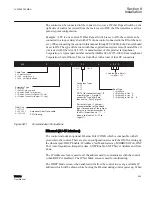
GUID-8D7A6A0B-17E5-4D1E-A569-464AEA047ECC V1 EN
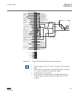
Figure 438:
External Connection Locations
The external connections for the control are made to the 24-pin connector, P2. For
example, if external dry contacts are being used to control the voltage reduction Step #1
function, connections for these contacts may be made between Pin 10 and Pin 18 as shown
in
. The dry contact inputs for non-sequential input, voltage reduction, motor
seal-in, counter input and neutral detection must be "wetted" by connecting to terminal Pin
10.
These binary inputs must be "wetted" by connection to Pin 10 only–a
nominal 12 Vdc source. If the contacts are connected to a 120 Vac source,
it will result in damage to the control.
Section 8
1VAC388793-MB A
Installation
552
TCC300
User Manual
Summary of Contents for TCC300
Page 1: ...Digital Tapchanger Control TCC300 User Manual ...
Page 2: ......
Page 3: ...Document ID 1VAC388793 MB Issued 2016 08 10 Revision A Copyright 2016 ABB All rights reserved ...
Page 26: ...20 ...
Page 34: ...28 ...
Page 91: ...1VAC388793 MB A Section 3 Operation TCC300 85 User Manual ...
Page 126: ...120 ...
Page 176: ...Section 4 1VAC388793 MB A TCC600 170 TCC300 User Manual ...
Page 260: ...254 ...
Page 328: ...322 ...
Page 494: ...488 ...
Page 556: ...550 ...
Page 580: ...574 ...
Page 600: ...594 ...
Page 700: ...694 ...
Page 710: ...704 ...
Page 712: ...706 ...
Page 713: ...707 ...
Page 714: ......
Page 715: ......