3-69
Default: [ ]
Rev.2.00
1
Before Using the Products
2
Preparation
3
Setup
4
Trial Run
5
Adjustment
6
When In T
roubie
7
Supplement
4. Details of Parameter
[Class 4] I/F Monitor Setting
*
1
The direction of monitor data is basically as defined in Pr 0.00 “Rotational direction setup”,However, the direction
of encoder rotational data is defined positive when it turns CCW.
*
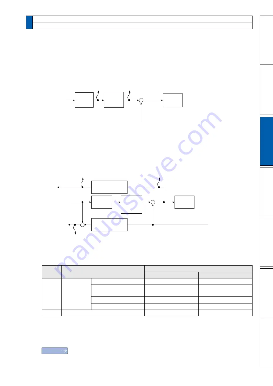
2 For the command pulse input, the speed before the positional command filter (smoothing, FIR filter) is defined as
positional command velocity and speed after filter is defined as internal command velocity.
Electronic
gear
Positional
command
filter
Position
control
Positional
command speed
[r/min]
Command
input
Internal position
command speed
[r/min]
+
-
Encoder feedback
*
3 The RTEX communication type (MINAS-A6N series) can set the calculation method (standard) for command
position deviation.
Switchover is accomplished according to the setting for the command position deviation output switching (bit 14) of
Pr7.23 “RTEX function extended setup 2”.
Pr7.23 bit14=0: Deviation with respect to command input after positional command filter
Pr7.23 bit14=1: Deviation with respect to command input before positional command filter
Electronic
gear
Positional
command
filter
Position
control
Command
input
+
+
-
-
Encoder feedback
Command position deviation [command unit]
(Pr7.23 bit14=1
)
Encoder positional deviation
[encoder unit]
Command position deviation
[command unit]
(Pr7.23 bit14=0
)
Electronic gear
reverse conversion
Electronic gear
reverse conversion
*
4 For monitor types No.23 and 24, digital signals are monitored using an analog monitor. Therefore, the output gain is as
follows irrespective of the settings for Pr4.17 “Analog monitor 1 output gain” and Pr4.19 “Analog monitor 2 output gain”.
<
Analog output setup
>
Pr4.16
/Pr4.18
Monitor type
Output voltage
0[V]
+5[V]
23
Travel
command
status
Profile position control (PP)
In process of profiling
Under suspension of profiling
Cyclic position control (CP)
Command update interval
Travel command ≠0
Command update interval
Travel command = 0
Cyclic velocity control (CV)
Velocity command ≠ 0
Velocity command = 0
Cyclic torque control (CT)
Torque command ≠ 0
Torque command = 0
24
Gain selection status
2nd gain(Including 3rd gain)
1st gain
*
5 The amount of motor power consumption per 30 minutes is output. The value is updated after the elapse of 30 minutes.
*
6 Regardless of the setting for Pr4.17 and Pr4.19, output gain shall be 0 V at unit 0 and 5 V at unit 1.
*
7 For CPU ver1.04/ver1.05 and ver1.20, unit is different.
Note
・
For description of “ command unit ” and “ encoder unit ” refer to P.3-85 “ Pr5.20 ” .
・
For command input mode
(
PP, CP, CV, CT
)
,refer to P.3-2 and P.3-3.
Содержание MINAS A6N Series
Страница 14: ...14 Rev 2 00 MEMO ...
Страница 30: ...1 16 Rev 2 00 MEMO ...
Страница 104: ...2 74 Rev 2 00 MEMO ...
Страница 228: ...3 124 Rev 2 00 MEMO ...
Страница 491: ...7 108 Rev 2 00 MEMO ...


