Memory rank sparing in lockstep mode
This information covers using the memory rank sparing feature of the lockstep
memory mode.
The server supports memory rank sparing. Memory rank sparing reserves memory
capacity for failover in the event of a DIMM failure, and the reserved capacity is
subtracted from the total available memory. Memory sparing provides less
redundancy than memory mirroring does. If a predetermined threshold of
correctable errors is reached, the contents of the failing DIMM are copied to the
spare memory, and the failing DIMM or rank is disabled.
To enable memory sparing through the Setup utility, select
System Settings
→
Memory
→
Memory Mode
. For more information, see “Using the Setup utility” on
page 126. For more information and notes about installing DIMMs, see “Installing
a memory module” on page 47
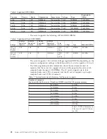
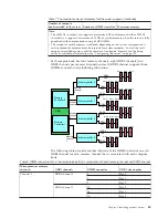
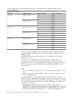
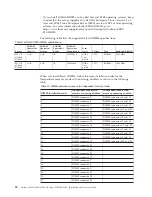
The DIMM installation order for memory rank sparing follows the independent
mode (performance) or lockstep mode (RAS) installation order based on the mode
of operation selected. For more information, see “Independent memory mode” on
page 55, and “Lockstep memory mode” on page 59.
Consider the following when using the memory rank sparing feature in
independent memory mode:
v
Memory rank sparing is not supported if memory mirroring is enabled.
v
The spare rank must have identical or larger memory capacity than all the other
ranks on the same DDR3 channel.
v
When single-rank DIMMs (that is, 4 GB and 8 GB) are used, a minimum of two
rank DIMMs must be installed per memory channel to support memory sparing.
v
When multi-rank DIMMs (that is, 16 GB, 32 GB, and 64 GB) are used, one
multi-rank DIMM can be installed per memory channel to support memory
sparing.
v
The total memory available in the system is reduced by the amount of memory
allocated for the spare ranks.
DIMM installation instructions
This information provides instructions on how to install DIMMs for
memory-mirroring mode.
Note:
v
The information and installation procedures in this documentation apply to both
the 4-socket and the 8-socket configurations of the server, unless otherwise
specified. Most of the illustrations in the documentation show the 4-socket
configuration of the server.
v
For additional information and notes that you need to consider when installing
DIMMs, see “Installing a memory module” on page 47 and “Flash DIMMs” on
page 51.
Attention: Static electricity that is released to internal server components when the
server is powered on might cause the server to stop, which might result in the loss
of data. To avoid this potential problem, always use an electrostatic-discharge wrist
strap and plug it into the electrostatic-discharge connector on the front of the
server (see “Front view of the server” on page 24 for the location of this connector)
or other grounding system when you work inside the server with the power on.
62
System x3850 X6 and x3950 X6 Types 3837 and 3839: Installation and Service Guide
Содержание X3850 X6
Страница 1: ...System x3850 X6 and x3950 X6 Types 3837 and 3839 Installation and Service Guide...
Страница 2: ......
Страница 3: ...System x3850 X6 and x3950 X6 Types 3837 and 3839 Installation and Service Guide...
Страница 138: ...120 System x3850 X6 and x3950 X6 Types 3837 and 3839 Installation and Service Guide...
Страница 225: ...25 26 27 Chapter 5 Parts listing System x3850 X6 and x3950 X6 Types 3837 and 3839 207...
Страница 1682: ...1664 System x3850 X6 and x3950 X6 Types 3837 and 3839 Installation and Service Guide...
Страница 1706: ...1688 System x3850 X6 and x3950 X6 Types 3837 and 3839 Installation and Service Guide...
Страница 1710: ...1692 System x3850 X6 and x3950 X6 Types 3837 and 3839 Installation and Service Guide...
Страница 1728: ...1710 System x3850 X6 and x3950 X6 Types 3837 and 3839 Installation and Service Guide...
Страница 1729: ......
Страница 1730: ...Part Number 00FH434 Printed in USA 1P P N 00FH434...

