


v
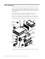
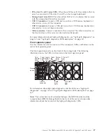
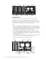
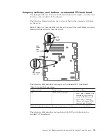
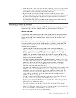
3V battery error LED:
When this LED is lit, it indicates that a standard I/O
book battery error has occurred.
v
Ethernet connectors:
Use either of these connectors to connect the server to a
network. When you use the Ethernet 1 connector, the network can be shared
with the IMM through a single network cable.
v
Ethernet activity LEDs:
When these LEDs are lit, they indicate that the server is
transmitting to or receiving signals from the Ethernet LAN that is connected to
the Ethernet port.
v
Ethernet link LEDs:
When these LEDs are lit, they indicate that there is an
active link connection on the 100BASE-TX, 1000BASE-TX, or 10GBASE-TX
interface for the Ethernet port.
v
Ethernet adapter slots:
Insert the dual-port or quad-port Ethernet adapters into
these slots.
v
I/O board error LED:
When this LED is lit, it indicates that an error has
occurred on the standard I/O book board.
v
Locate LED:
Use this LED to visually locate the server among other servers. You
can use IBM Systems Director to light this LED remotely. IMM can also be used
to turn this LED on and off. This LED is functionally equivalent to the locate
LED on the front of the server.
v
NMI button:
Press this button to force a nonmaskable interrupt to the
microprocessor. You might have to use a pen or the end of a straightened paper
clip to press the button. You can also use it to force a blue-screen memory
dump. Use this button only when you are directed to do so by IBM Support.
v
Serial connector:
Connect a 9-pin serial device to this connector. The serial port
is shared with the integrated management module (IMM). The IMM can take
control of the shared serial port to redirect serial traffic, using Serial over LAN
(SOL).
v
System-error LED:
When this LED is lit, it indicates that a system error has
occurred. An LED on the front operator panel is also lit to help isolate the error.
This LED is functionally equivalent to the system-error LED on the front of the
server.
v
Systems-management Ethernet connector:
Connect to this connector to manage
the server, by using a dedicated management network. If you use this connector,
the IMM cannot be accessed directly from the production network. A dedicated
management network provides additional security by physically separating the
management network traffic from the production network. You can use the
Setup utility to configure the server to use a dedicated systems-management
network or a shared network.
v
USB 2.0 connectors:
Connect a USB device, such as a USB mouse, keyboard, or
other device, to any of these connectors.
v
Video connector:
Connect a monitor to this connector. The video connectors on
the front and rear of the server can be used simultaneously.
Note:
The maximum video resolution is 1600 x 1200 at 75 Hz.
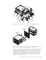
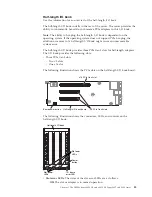
The following is an illustration of the standard I/O book board:
Chapter 1. The IBM System x3850 X6 and x3950 X6 Types 3837 and 3839 server
33
Содержание X3850 X6
Страница 1: ...System x3850 X6 and x3950 X6 Types 3837 and 3839 Installation and Service Guide...
Страница 2: ......
Страница 3: ...System x3850 X6 and x3950 X6 Types 3837 and 3839 Installation and Service Guide...
Страница 138: ...120 System x3850 X6 and x3950 X6 Types 3837 and 3839 Installation and Service Guide...
Страница 225: ...25 26 27 Chapter 5 Parts listing System x3850 X6 and x3950 X6 Types 3837 and 3839 207...
Страница 1682: ...1664 System x3850 X6 and x3950 X6 Types 3837 and 3839 Installation and Service Guide...
Страница 1706: ...1688 System x3850 X6 and x3950 X6 Types 3837 and 3839 Installation and Service Guide...
Страница 1710: ...1692 System x3850 X6 and x3950 X6 Types 3837 and 3839 Installation and Service Guide...
Страница 1728: ...1710 System x3850 X6 and x3950 X6 Types 3837 and 3839 Installation and Service Guide...
Страница 1729: ......
Страница 1730: ...Part Number 00FH434 Printed in USA 1P P N 00FH434...


