Chapter 11 Motion Control Instructions
11-195
11
There are three modes of
StartMode
for selection: the shortest way (mcRamplnShortest), positive
direction (mcRamplnPositive) and negative direction (mcRamplnNegative)
.
Users can select the right
engagement mode according to actual need.
StartMode=0
(
The shortest way)
As
StartMode
=0, in the execution of the engagement action, the slave axis moves toward the
position for synchronization by taking the shortest way. At the moment, the motion of the
slave axis is affected by the
Velocity, Acceleration Deceleration
and
Jerk
parameters.
StartMode=1
(
Positive direction
)
As
StartMode
=1, in the execution of the engagement action, the slave axis moves toward the
position for synchronization in the positive direction. At the moment, the motion of the slave
axis is affected by the
Velocity, Acceleration Deceleration
and
Jerk
parameters.
StartMode=-1
(
Negative direction
)
As
StartMode
=-1, in the execution of the engagement action, the slave axis moves toward
the position for synchronization in the negative direction. At the moment, the motion of the
slave axis is affected by the
Velocity, Acceleration Deceleration
and
Jerk
parameters.
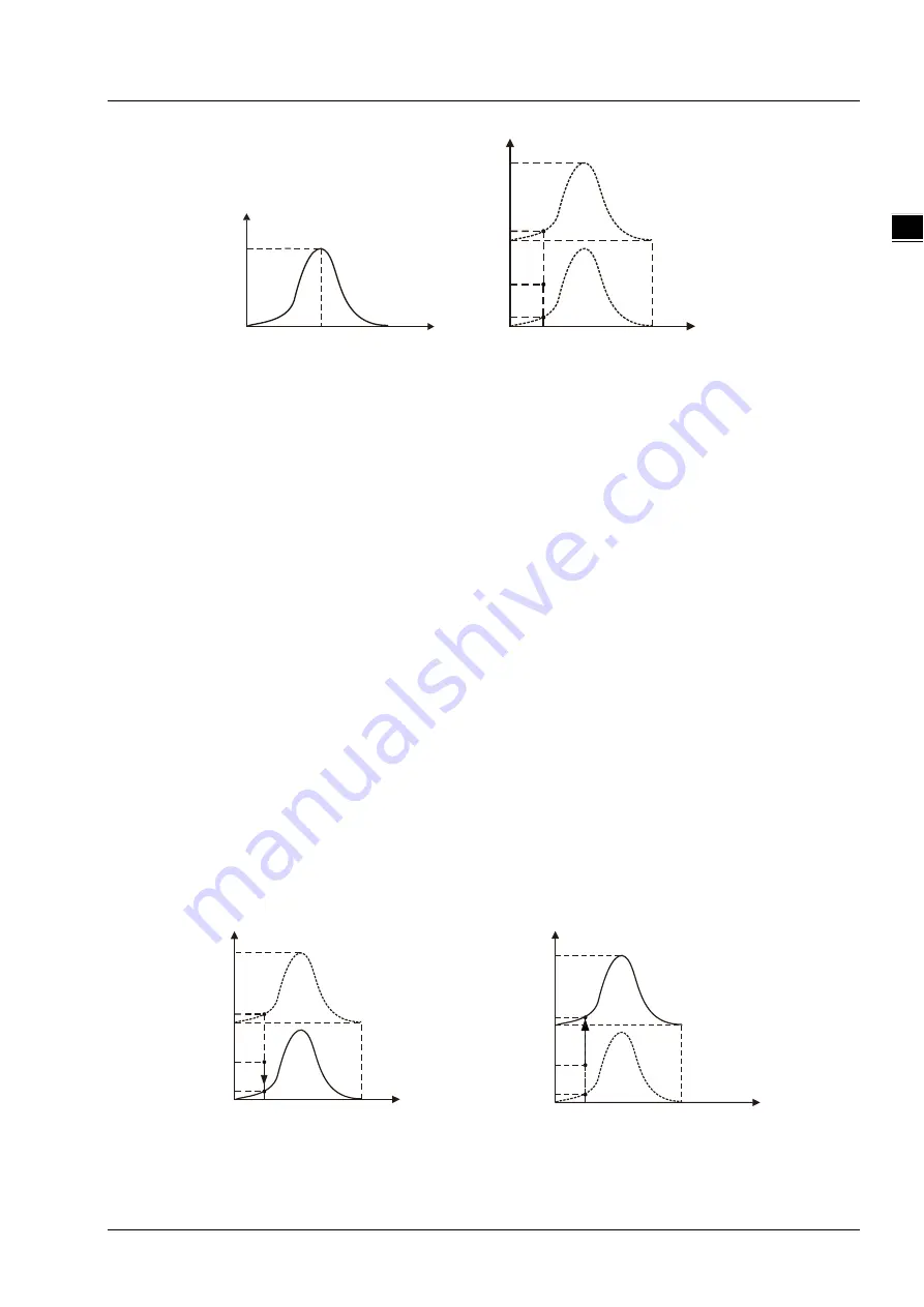
For example,
as the engagement begins, the master axis cam phase and slave axis cam phase
are 80 and 180 respectively (as point O below). According to the defined cam relationship, the
master axis cam phase is 80 and the slave axis cam phase is 40 (as point A or B below). If the
value of
StartMode
is different, the way the slave axis moves is different in the engagement
process.
StartMode
=0
:
The slave axis moves from point O to point A and the synchronization is achieved
at point A since the distance from point O to point A is less than that from point O
to point B.
StartMode
=1
:
The slave axis gradually moves from point O to point B in the positive direction.
StartMode
=-1
:
The slave axis gradually moves from point O to point A in the negative direction.
Slave ax is phase
Mas t er
ax is phas e
0
180
360
300
Plann ed Cam C urv e
Slav e axis posit ion
(
)
Slav e ax is phas e
M ast er ax is pos it ion
(
Mas t er ax is phas e)
360
(360)
180 (180)
360 (0)
66 0(300)
0 (0)
B
A
o
80
(80)
40(40)
40 0(40)
S
lave axis position
(S
lave axis ph ase )
M
ast er ax is pos it ion
( aste r
M
axis pha se)
360
(360)
18 0(180)
360(0)
660 (30 0)
0( 0)
B
A
o
80
(80)
40(40)
400 (40)
St art Mode=0
M
as ter ax is posit ion
( aster
M
axis phas e)
360
(360)
180(180)
360 (0)
660(300)
0(0)
B
A
o
80
(80)
40 (40)
400 (40)
St art Mode=1
S
lave axis position
(S
lave axis pha se)
Содержание DVP-15MC Series
Страница 16: ...1 1 1 Preface Table of Contents 1 1 Explanation of Symbols in This Manual 1 2 1 2 Revision History 1 3...
Страница 19: ...DVP 15MC Series Motion Controller Operation Manual 1 4 _1 MEMO...
Страница 20: ...2 1 2 Overview Table of Contents 2 1 Product Description 2 2 2 2 Functions 2 2 2 3 Profile and Components 2 3...
Страница 23: ...DVP 15MC Series Operation Manual 2 4 _2 MEMO...
Страница 31: ...DVP 15MC Series Motion Controller Operation Manual 3 8 _3 MEMO...
Страница 75: ...DVP 15MC Series Motion Controller Operation Manual 6 26 _6 MEMO...
Страница 87: ...DVP 15MC Series Motion Controller Operation Manual 7 12 _7 MEMO...
Страница 432: ...Chapter 8 Logic Instructions 8 345 8_ MEMO...
Страница 433: ...9 1 9 Chapter 9 Introductions of Axis Parameters Table of Contents 9 1 Description of Axis Parameters 9 2...
Страница 470: ...DVP 15MC Series Motion Controller Operation Manual 10 34 10 MEMO...
Страница 878: ...DVP 15MC Series Motion Controller Operation Manual 11 408 11 1 MEMO...
Страница 920: ...DVP 15MC Series Motion Controller Operation Manual A 16 A MEMO...
Страница 941: ...D 1 D Explanation of Homing Modes Table of Contents D 1 Explanation of Homing Modes D 2...
Страница 966: ...DVP 15MC Series Motion Controller Operation Manual D 26 D MEMO...


