Chapter 8 Logic Instructions
8-315
8_
whether the scan time reaches the sampling time specified by
CYCLE
so as to output.
The present value (PV) of PID must be a steady value before PID operation is performed. If the
input values of special modules are to be captured for PID operation, users should notice the A/D
conversion time of modules.
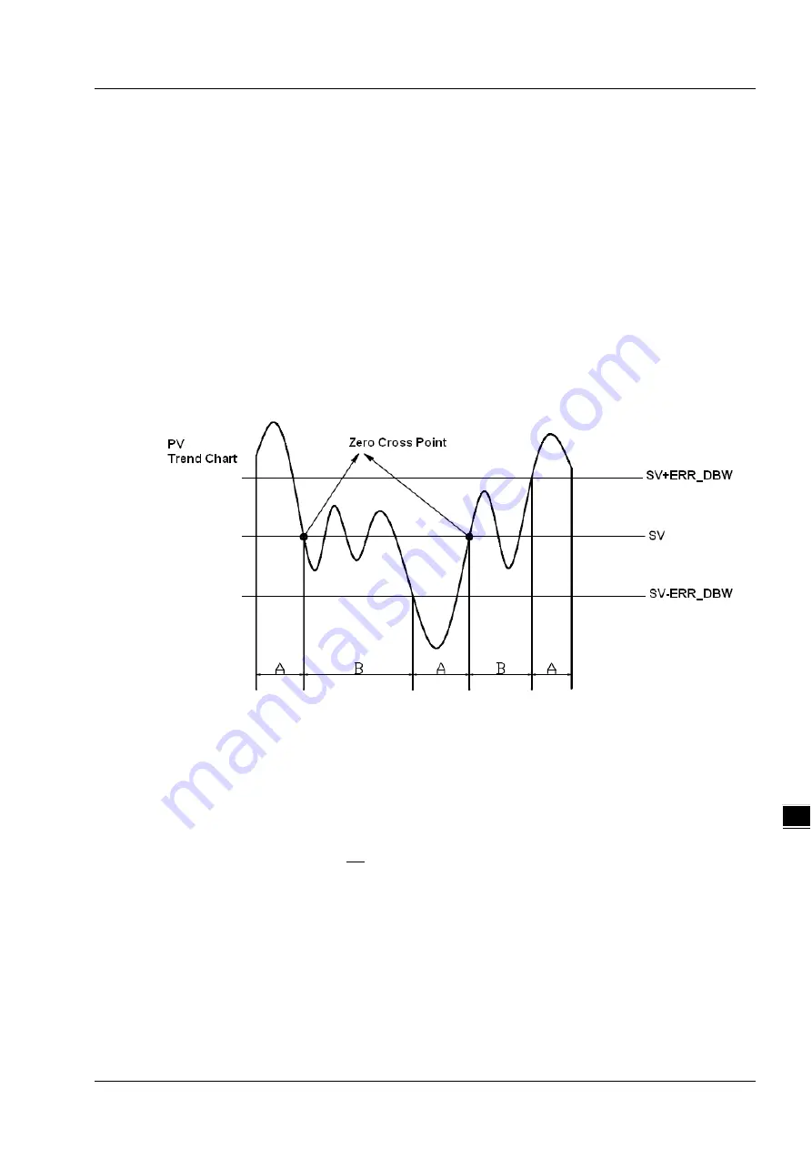
When the PV value is in the range of
ERR_DBW
, at the beginning, the present error will be brought
into the PID operation according to the normal processing and then the PLC module will check
whether the present error meets the cross status condition: PV (process value) passes by the SV
(target value). Once the condition is met, the present error will be counted as 0 for the PID operation.
And after the PV value is out of the
ERR_DBW
range, the present error will be brought into the PID
operation again.
If PID_DE is TRUE, that means using the the PV value to calculate the control value of the derivative
and after the cross status condition is met, the PLC will treat
Δ
PV
as 0 to implement the PID operation.
(Δ
PV
= current
PV
– previous
PV
). As the example shown below, the present error will be brought
into the PID opeation according to the normal processing in the section A and the present error or
Δ
PV
will be counted as 0 to implement the PID operation in the section B.
PID Algorithm:
When
PID_MODE
is set to 0, the PID control mode is the automatic control mode
I n d e p e n d e n t F o r m u l a & D e r i v a t i v e o f E
(
P I D _ E Q
= F a l s e &
P I D _ D E
= F a l s e
)
BIAS
dt
dE
K
dt
E
Ki
E
K
MV
d
t
P
+
+
+
=
∫
*
0
E = S V – P V
o r
E = P V – S V
When
PID_MODE
is set to 1, the PID control mode is the automatic tuning mode. After the
tuning of the parameter is completed,
PID_MODE
becomes 0 automatically and the PID control
mode becomes the automatic control mode
Содержание DVP-15MC Series
Страница 16: ...1 1 1 Preface Table of Contents 1 1 Explanation of Symbols in This Manual 1 2 1 2 Revision History 1 3...
Страница 19: ...DVP 15MC Series Motion Controller Operation Manual 1 4 _1 MEMO...
Страница 20: ...2 1 2 Overview Table of Contents 2 1 Product Description 2 2 2 2 Functions 2 2 2 3 Profile and Components 2 3...
Страница 23: ...DVP 15MC Series Operation Manual 2 4 _2 MEMO...
Страница 31: ...DVP 15MC Series Motion Controller Operation Manual 3 8 _3 MEMO...
Страница 75: ...DVP 15MC Series Motion Controller Operation Manual 6 26 _6 MEMO...
Страница 87: ...DVP 15MC Series Motion Controller Operation Manual 7 12 _7 MEMO...
Страница 432: ...Chapter 8 Logic Instructions 8 345 8_ MEMO...
Страница 433: ...9 1 9 Chapter 9 Introductions of Axis Parameters Table of Contents 9 1 Description of Axis Parameters 9 2...
Страница 470: ...DVP 15MC Series Motion Controller Operation Manual 10 34 10 MEMO...
Страница 878: ...DVP 15MC Series Motion Controller Operation Manual 11 408 11 1 MEMO...
Страница 920: ...DVP 15MC Series Motion Controller Operation Manual A 16 A MEMO...
Страница 941: ...D 1 D Explanation of Homing Modes Table of Contents D 1 Explanation of Homing Modes D 2...
Страница 966: ...DVP 15MC Series Motion Controller Operation Manual D 26 D MEMO...


