BODY IB-51
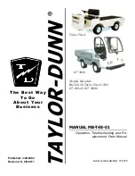
STRIKER BOLT MARK
IN PAINT OR GREASE
DOOR STRIKER
CAM MARK
SCRIBE HORIZONTAL LINE
APPLY PAINT OR GREASE
F ig . 119—S trik e r B o lt A lig n m e n t Points
2. In sert a 5/16-inch hex wrench into head of s trik e r
bolt, then turn bolt cou n terclockw ise fro m plate in
cab p illa r.
3. R e v e rs e above procedu re to in stall. Make sure the
thin p la stic w asher is positioned against the painted
door opening p illa r and center the bolt w asher within
m arks on p illa r.
4. If door has been rem o ved and then in stalled or
aligned in opening, the door should not be closed
com p letely until a visu al check is made to determ ine
if lock cam in door w ill engage the s trik e r bolt c o r-
F ig . 120—S ight C h e c k in g S trik e r B olt A lig n m e n t
re c tly . C enter of s tr ik e r bolt should be in d ire c t
alignment with
“ V ”
slot in door. If n ecessary, r e
position s trik e r bolt as d irected below under " S t r ik e r
Bolt Adjustm ent.”
Striker Bolt A djustm ent
NOTE:
S trik er bolt on cab p illa r is adjustable
v e r tic a lly and tra n s v e rs e ly after loosening the
bolt with a 5/16-inch hex wrench. The bolt fo r e
and aft adjustment is obtained by use of shim
sp acers located between the bolt w asher and the
cab p illa r, F igu re 118.
Striker Bolt “ Fore” and “ A ft” Adjustm ent
1. T o check s tr ik e r bolt fo r prop er fo r e and aft adjust
ment, sm ea r gre a s e or paint to contact side of bolt
(fig . 119)
2. Slowly close door until lock cam of door just con
tacts the side of s trik e r bolt and makes an im p re s
sion in the grea se or paint.
3. M easure distance between head of bolt and the cam
im p ression in grea se.
Distance should m easure
l/8 -in ch as shown in fig u re 120. This dim ension
is n ecessa ry to assure that the head of s tr ik e r bolt
w ill rid e at cen ter of nylon shoe which is located
just in back of the lock cam.
T o obtain this dim ension, rem ove the s trik e r bolt
and in stall o r rem ove shim spacers. Spacers are
available in two thicknesses: 5/64-inch and 5/32-
inch. Make sure the thin p la stic w asher is located
next to cab p illa r.
CHEVROLET TRUCK SERVICE MANUAL
Содержание 10 Series 1970
Страница 1: ......
Страница 38: ...HEATER AND AIR CONDITIONING 1A 8 CHEVROLET TRUCK SERVICE MANUAL...
Страница 57: ...HEATER AND AIR CONDITIONING 1A 27 Fig 35 Compressor M ountings CHEVROLET TRUCK SERVICE MANUAL...
Страница 75: ...HEATER AND AIR CONDITIONING 1A 45 Fig 65 R oof M ounted System W iring Diagram CHEVROLET TRUCK SERVICE MANUAL...
Страница 78: ......
Страница 101: ...BODY IB 23 s A ADJUSTER SCREW AND LEVER ASSY Fig 5 9 Exploded V iew o f Level Ride Seat CHEVROLET TRUCK SERVICE MANUAL...
Страница 137: ...BODY IB 59 VIEW IN DIRECTION OF ARROW A Fig 137 A u x ilia ry Seat CHEVROLET TRUCK SERVICE MANUAL...
Страница 142: ...CHEVROLET TRUCK SERVICE MANUAL Fig 5 10 30 Series Truck Frame FRAME 2 4...
Страница 145: ...CHEVROLET TRUCK SERVICE MANUAL FRAME 2 7...
Страница 148: ......
Страница 228: ...REAR SUSPENSION AND DRIVE LINE 4 52 I Fig 88 Forward Rear A xle Assembly Exploded V iew CHEVROLET TRUCK SERVICE MANUAL...
Страница 238: ......
Страница 383: ...ENGINE FUEL 6M 19 F ig I t Engine Fuel S p ecial Tools CHEVROLET TRUCK SERVICE MANUAL...
Страница 384: ......
Страница 392: ......
Страница 432: ...Fig 1 C lu tch Linkage Except P 2 0 4 0 Series...
Страница 433: ...CLUTCHES AND TRANSMISSIONS 7 3 Fig 2 C lutch Linkage Step Van P 20 40 Series CHEVROLET TRUCK SERVICE MANUAL...
Страница 506: ...FUEL TANK AND EXHAUST SYSTEMS 8 8 Fig 10 Vent Lines Cab M ounted Tanks CHEVROLET TRUCK SERVICE MANUAL...
Страница 528: ...Fig 31 T yp ica l Power Steering Hose Routings...
Страница 530: ......
Страница 550: ......
Страница 566: ...ELECTRICAL BODY AND CHASSIS 12 4 Fig 3 Front Lighting Assemblies CHEVROLET TRUCK SERVICE MANUAL...
Страница 567: ...ELECTRICAL BODY AND CHASSIS 12 5 Fig 4 C learance and Id e n tific a tio n Lamps CHEVROLET TRUCK SERVICE MANUAL...
Страница 568: ...ELECTRICAL BODY AND CHASSIS 12 6 Fig 5 Rear Lighting Composite CHEVROLET TRUCK SERVICE MANUAL...
Страница 597: ...ELECTRICAL BODY AND CHASSIS 12 35 Fig 37 Engine Com partm ent CE M E60 CHEVROLET TRUCK SERVICE MANUAL...
Страница 598: ...ELECTRICAL BODY AND CHASSIS 12 36 TO FRAME i f Fig 38 Engine Com partm ent C D 50 CHEVROLET TRUCK SERVICE MANUAL...
Страница 608: ...ELECTRICAL BODY AND CHASSIS 12 46 Fig 48 Instrument Panel C A40 CE CS ME50 Exc 02 CHEVROLET TRUCK SERVICE MANUAL...
Страница 610: ...ELECTRICAL BODY AND CHASSIS 12 48 Fig 50 Instrument Panel CE M E60 03 13 CHEVROLET TRUCK SERVICE MANUAL...
Страница 614: ...ELECTRICAL BODY AND CHASSIS 12 52 Fig 54 Instrument Panel SA40 50 CHEVROLET TRUCK SERVICE MANUAL...
Страница 628: ......
Страница 640: ......
Страница 649: ...SPECIFICATIONS 9 ENGINE SECTION 6 CHEVROLET TRUCK SERVICE MANUAL...
Страница 671: ......