background image

11-2

 Parameterization

Rexroth IndraDrive FCS01.1

           DOK-INDRV*--FCS01*****-IB01_EN-P

CAUTION

All current parameter setting will be lost if P523 = 1 is
set and confirmed with "ENTER". To save current
settings, they can be transferred to the memory of
the control panels.

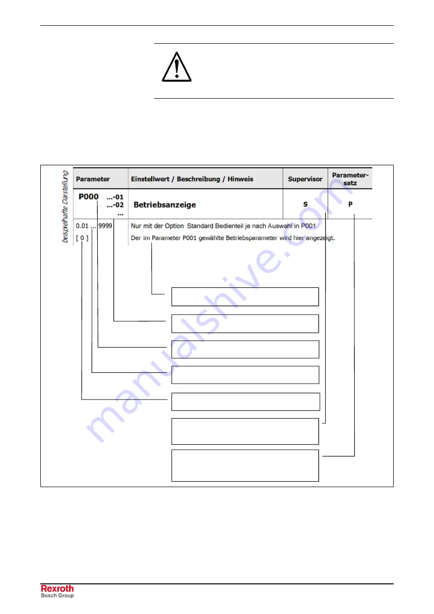
Availability of Parameters

Depending on the respective configurations, the parameters are subject
to certain conditions. In the following table pages (from Chapter 11.1
Status Indication), all parameters are listed with the respective
information.

Supervisor parameter depend upon the
setting in P003

Parameter number

Parameter text

Parameter record dependent parameter

selection in P100

Array values

Value range of the parameter

Factory setting of the parameter

Fig. 11-2:

Availability of parameters

Summary of Contents for IndraDrive Fc FCS01

Page 1: ...oth IndraDrive Fc Drive Controllers Frequency Converters FCS01 R911310845 Edition 01 Operating Instructions Electric Drives and Controls Pneumatics Service Linear Motion and Assembly Technologies Hydraulics ...

Page 2: ...contents thereof without express authority are forbidden Offenders are liable for the payment of damages All rights are reserved in the event of the grant of a patent or the registration of a utility model or design DIN 34 1 The specified data is for product description purposes only and may not be deemed to be guaranteed unless expressly confirmed in the contract All rights are reserved with resp...

Page 3: ...ers 2 5 Protection Against Contact with Electrical Parts 2 5 2 4 Protection Against Electric Shock by Protective Low Voltage PELV 2 7 2 5 Protection Against Dangerous Movements 2 7 2 6 Protection Against Magnetic and Electromagnetic Fields During Operation and Mounting 2 9 2 7 Protection Against Contact with Hot Parts 2 10 2 8 Protection During Handling and Mounting 2 11 2 9 Battery Safety 2 11 2 ...

Page 4: ...12 X31 Relay 1 1 2 Relay 2 3 4 8 13 X5 Connection of Motor Cable PE U V W 8 13 X5 Connection of Braking Resistor B B 8 14 X5 DC Coupling B DC 8 15 Settings to Reduce the Leakage Currents 8 16 8 5 Electrical Control Connectors 8 18 9 Indications and Operation of the Function Modules 9 1 9 1 Indicator Elements at the FCS01 Basic Device 9 1 9 2 Modules FCC01 9 1 9 3 Overview over FCC01 Function Modul...

Page 5: ...tromagnetic Compatibility EMC 13 9 Realizable EMC Limit Value Classes in preparation 13 10 14 Additional Information 14 1 14 1 Setpoint Processing in FCS01 14 1 14 2 Process Controller 14 2 Sample application process controller 14 3 Process Controller Parameter Settings 14 4 15 Control Communication Field Busses and Protocols 15 1 15 1 Overview 15 1 15 2 Profibus DP 15 2 Profibus Protocol 15 2 Pro...

Page 6: ...P Telegram Structure 15 48 USIP Data Transfer Sample Telegrams 15 49 USIP Data Transfer Status Machine 15 54 USIP Data Transfer Master Telegram Times 15 55 15 5 DeviceNet 15 56 DeviceNet Protocol 15 56 DeviceNet Bus Description 15 57 DeviceNet Parameterization 15 58 DeviceNet Error Monitoring and Indication 15 60 DeviceNet Telegram Structure 15 61 DeviceNet Data Transfer Status Machine 15 62 Devic...

Page 7: ...ve system Rexroth IndraDrive Fc help for selecting the system components of the drive system Rexroth IndraDrive Fc These Operating Instructions comprise information on Assembly and installation Technical data of the individual components as far as relevant for the operation Current voltage and performance data Dimensions and weights and Pin assignment This documentation contains safety regulations...

Page 8: ...rror Messages 13 Technical Data 14 Additional Information 15 Control Communication Field Busses and Protocols Practical application for operators and maintenance staff 16 Disposal and Environmental Protection General Information Fig 1 1 Main focuses of the Chapters 1 2 Abbreviations Used This documentation uses the following abbreviations Abbr Significance Contents FC Frequency converter PPO Param...

Page 9: ...ds for the first version of a system configuration Fig 1 3 Documentations overview Standards German European and international technical standards are mentioned in this documentation Standard documents and sheets are subject to copyright protection and Rexroth mustn t pass them on If required contact the authorized sales agencies in Germany directly contact BEUTH Verlag GmbH Burggrafenstrasse 6 10...

Page 10: ...DLT optional 1 phase NFE optional mains filter 3 phase NFD03 1 HNF01 1 optional mains choke standard FNL01 1E optional Frequency converter single axis FCS01 1 standard firmware FCB01 standard control panels FCC01 1T optional Function module Field bus module FCC01 1F optional Braking resistor FLR01 1 optional Output throttle FML01 optional shielded RKL standard Motor cable unshielded RKL optional M...

Page 11: ... instructions at all times Bosch Rexroth AG is not liable for damages resulting from failure to observe the warnings provided in this documentation Read the operating maintenance and safety instructions in your language before starting up the machine If you find that you cannot completely understand the documentation for your product please ask your supplier to clarify Proper and correct transport...

Page 12: ...l application and check the information given in this documentation with regard to the use of the components make sure that his application complies with the applicable safety regulations and standards and carry out the required measures modifications and complements Startup of the delivered components is only permitted once it is sure that the machine or installation in which they are installed c...

Page 13: ...ees of hazard seriousness The degree of hazard seriousness informs about the consequences resulting from non compliance with the safety instructions Warning symbol with signal word Degree of hazard seriousness according to ANSI Z 535 DANGER Death or severe bodily harm will occur WARNING Death or severe bodily harm may occur CAUTION Bodily harm or material damage may occur Fig 2 1 Hazard classifica...

Page 14: ...ntentional motor movements WARNING High electric voltage because of incorrect connection Risk of death or bodily injury by electric shock WARNING Health hazard for persons with heart pacemakers metal implants and hearing aids in proximity to electrical equipment CAUTION Hot surfaces on device housing Danger of injury Danger of burns CAUTION Risk of injury by improper handling Risk of bodily injury...

Page 15: ... trained and qualified to work with or on electrical equipment are permitted to operate maintain and repair this equipment Follow general construction and safety regulations when working on electrical power installations Before switching on the device the equipment grounding conductor must have been non detachably connected to all electrical equipment in accordance with the connection diagram Do n...

Page 16: ...rnal housing for example a control cabinet European countries according to EN 50178 1998 section 5 3 2 3 USA See National Electrical Code NEC National Electrical Manufacturers Association NEMA as well as local engineering regulations The operator must observe all the above regulations at any time With electrical drive and filter components observe the following DANGER High housing voltage and larg...

Page 17: ...ers or battery operation without mains connection 2 5 Protection Against Dangerous Movements Dangerous movements can be caused by faulty control of connected motors Some common examples are improper or wrong wiring of cable connections incorrect operation of the equipment components wrong input of parameters before operation malfunction of sensors encoders and monitoring devices defective componen...

Page 18: ...tally entering the machine s range of motion use safety fences use safety guards use protective coverings install light curtains or light barriers Fences and coverings must be strong enough to resist maximum possible momentum Mount the emergency stop switch in the immediate reach of the operator Verify that the emergency stop works before startup Don t operate the device if the emergency stop is n...

Page 19: ...ctromagnetic fields generated by current carrying conductors and permanent magnets in motors represent a serious personal danger to those with heart pacemakers metal implants and hearing aids WARNING Health hazard for persons with heart pacemakers metal implants and hearing aids in proximity to electrical equipment Persons with heart pacemakers and metal implants are not permitted to enter followi...

Page 20: ...ccessing motors after having switched them off let them cool down for a sufficiently long time Cooling down can require up to 140 minutes Roughly estimated the time required for cooling down is five times the thermal time constant specified in the Technical Data After switching drive controllers or chokes off wait 15 minutes to allow them to cool down before touching them Wear safety gloves or do ...

Page 21: ...s safety shoes safety gloves Do not stand under hanging loads Immediately clean up any spilled liquids because of the danger of skidding 2 9 Battery Safety Batteries consist of active chemicals enclosed in a solid housing Therefore improper handling can cause injury or damages CAUTION Risk of injury by improper handling Do not attempt to reactivate low batteries by heating or other methods risk of...

Page 22: ...s supply lines or connections can cause injuries or damages CAUTION Risk of injury by improper handling of pressurized lines Do not attempt to disconnect open or cut pressurized lines risk of explosion Observe the respective manufacturer s operating instructions Before dismounting lines relieve pressure and empty medium Use suitable protective equipment for example safety goggles safety shoes safe...

Page 23: ... the guarantee and the right to payment of damages resulting from inappropriate use are forfeited The user alone carries all responsibility of the risks Before using Rexroth products make sure that all the pre requisites for an appropriate use of the products are satisfied Personnel that in any way shape or form uses our products must first read and understand the relevant safety instructions and ...

Page 24: ...ic use the drive controllers are available with different drive power and different interfaces Typical applications of the drive controllers include handling and mounting systems packaging and food machines printing and paper processing machines and machine tools The drive controllers may only be operated under the assembly and installation conditions described in this documentation in the specifi...

Page 25: ...ed in parameter P707 If your frequency converter is of another version differences may occur In this case download the latest manual and device software from http www boschrexroth com indradrive 4 2 FCS01 Properties FCS01 Properties of the basic device FCS01 Permitted ambient temperature 0 to 50 C Degree of protection IP20 for installation of control cabinet Can be mounted next to each other witho...

Page 26: ... online operation PID and process controller 32 fixed frequencies Motor potentiometer Signal recording Programmable d c braking Ramp rounding Flying restart circuit Interfaces RS 232 RS 485 5 digital inputs 2 analog inputs can also be used as digital input 1 analog output 2 relays AC230V DC30V 2A Cooling Types Depending on Size Natural cooling Forced temperature controlled cooling ...

Page 27: ... energy recovery function FAS01 temperature switch for assembly to FLR01 braking resistors FAS02 optional component for connection of the motor cable shield to the housing of the frequency converter DriveTop Fc software for parameterization and commissioning Ask us for any other accessories you may require FCC01 1T STD NNNN standard control panel removable control panel 4 digit 7 segment LED displ...

Page 28: ...5 2 Delivery Rexroth IndraDrive FCS01 1 DOK INDRV FCS01 IB01_EN P ...

Page 29: ...ty EMC UL and cUL Certification The registration of the FCS01 frequency converter is under preparation application in North America Fig 6 2 UL and cUL certification Suitable for use on a circuit capable of delivering not more than 5000 rms symmetrical amperes 200 240 Volts or 380 480 Volts three phase and when protected by J class fuses as indicated in Chapter 7 4 The FCS01 frequency converters of...

Page 30: ...e FCS01 1 DOK INDRV FCS01 IB01_EN P 6 2 Type Codes Type Code Frequency Converter FCS01 1 Maximum current 0025 an 0032 is not available with mains connecting voltage 02 Fig 6 3 Type code FCS01 Type Code FCC01 Function Module Fig 6 4 Type code FCS01 ...

Page 31: ...oth IndraDrive FCS01 1 Certifications and Types 6 3 DOK INDRV FCS01 IB01_EN P Type Code FLR01 Braking Resistor Fig 6 5 FLR01 type code Accessories FAS01 Type Code Temperature Switch Fig 6 6 Type code FAS01 ...

Page 32: ...6 4 Certifications and Types Rexroth IndraDrive FCS01 1 DOK INDRV FCS01 IB01_EN P Accessories FAS02 Type Code Shield Connection Fig 6 7 Type code FAS02 ...

Page 33: ... and Types 6 5 DOK INDRV FCS01 IB01_EN P 6 3 IndraDrive Fc Components Optional modules FCC01 Wall mounting bracket Optionales accessory FAS02 shield connector FLR01 braking resistor and FAS01 temperature switch Fig 6 8 IndraDrive Fc Components ...

Page 34: ...6 6 Certifications and Types Rexroth IndraDrive FCS01 1 DOK INDRV FCS01 IB01_EN P ...

Page 35: ... minimum distance above and below the frequency converter and to neighboring components which may disturb the free flow of air Note Mounting without additional lateral space between the frequency converters is permitted The installation position is always vertical 100mm 100mm Fig 7 1 Vertical installation position Note Warm air must be carried off above the devices If several frequency converters ...

Page 36: ...uency converter will occur 7 2 Dimensions of the FCS01 Frequency Converter Housing dimensions mm Wall mounting bracket mm Device type Size L W D L1 approx FCS01 1E W0003 A 02 FCS01 1E W0005 A 02 FCS01 1E W0006 A 02 FCS01 1E W0008 A 02 FCS01 1E W0003 A 04 FCS01 1E W0005 A 04 A 186 74 153 220 5 5 FCS01 1E W0011 A 02 FCS01 1E W0015 A 02 FCS01 1E W0019 A 02 FCS01 1E W0006 A 04 FCS01 1E W0011 A 04 B 22...

Page 37: ...re inserted at the heatsink at the rear of the device as shown in the illustration No other accessories are required Alternatively the wall mounting bracket can be inserted laterally at the heatsink to reduce the installation depth of the device to a minimum if required Note To ensure trouble free operation the device should be mounted vertically to a level surface Fig 8 1 Wall mounting bracket FC...

Page 38: ...re resistors FLR01 1U can be used The resistor can additionally be equipped with an optional temperature switch FAS01 to prevent overloading The fastening material in the groove on the side is comprised in the delivery range of the FLR01 1N The braking resistor and the temperature switch are connected via lines Size A Size B Fig 8 2 FLR01 substructure type For frequency converters with a power ran...

Page 39: ...06 A 02 NNBV FCS01 1E W0008 A 02 NNBV FLR01 1U 0200 N75R0 A 004 NNNN FCS01 1E W0011 A 02 NNBV FCS01 1E W0019 A 02 NNBV FLR01 1U 0100 N400R A 007 NNNN FCS01 1E W0003 A 04 NNBV FCS01 1E W0005 A 04 NNBV FLR01 1U 0200 N220R A 007 NNNN FCS01 1E W0006 A 04 NNBV FCS01 1E W0011 A 04 NNBV FLR01 1N 0400 N100R A 007 NNNN FCS01 1E W0015 A 04 NNBV FCS01 1E W0019 A 04 NNBV FLR01 1N 0600 N60R0 A 007 NNNN FCS01 1...

Page 40: ... A IP40 240 100 1 0 0 7 7 2 0 5 1 9 14 FLR01 1U 0100 N150R A 004 NNNN Substructure A IP40 150 100 1 0 1 1 4 2 0 5 1 9 14 FLR01 1U 0200 N75R0 A 004 NNNN Substructure A IP40 75 200 4 0 2 3 4 2 0 5 1 9 14 FLR01 1U 0100 N400R A 007 NNNN Substructure B IP40 400 100 0 75 3 8 0 5 2 0 5 1 9 14 FLR01 1U 0200 N220R A 007 NNNN Substructure B IP40 220 200 4 0 6 7 0 5 2 0 5 1 9 14 FLR01 1N 0400 N100R A 007 NNN...

Page 41: ... mm AWG mm AWG AC250V 2 5A cosPhi 1 1 6A cosPhi 0 6 AC250V 2A AC11 FAS01 1 001 TMP NN IP40 DC24V 2A DC11 1 B1 B 10 2 0 5 0 8 18 Optional equipment for FLR01 1U braking resistors AC250V 2 5A cosPhi 1 1 6A cosPhi 0 6 AC250V 2A AC11 Integrated in FLR01 1N IP40 DC24V 2A DC11 2 4 Integrated in FLR01 1N braking resistors 1 see FLR01 1U dimensions Fig 8 6 Technical data temperature switch Note The bimeta...

Page 42: ...1 1U Type of braking resistor Size A B C 1 D Diameter of fastening mm mm mm mm mm FLR01 1U 0100 N240R A 004 NNNN FLR01 1U 0100 N150R A 004 NNNN FLR01 1U 0200 N75R0 A 004 NNNN A 230 88 175 220 5 5 FLR01 1U 0100 N400R A 007 NNNN FLR01 1U 0200 N220R A 007 NNNN B 270 88 175 260 5 5 1 Installation depth of the frequency converter incl FLR01 1N Fig 8 8 Dimensions of FLR01 1N Dimensions of FLR01 1N type ...

Page 43: ...es is lower If possible the PE ground of the motor controlled through the frequency converter should be connected directly to the earth connection linked to the heat sink together with the PE of the power input line of the respective frequency converter Usually smooth operation is guaranteed if a central grounding bar is provided and all PEs are connected to this bar also see Chapter 13 4 Electrom...

Page 44: ...cy converter Wiring Arrangement and Shielding at Function Modules Where no EMC measures have been taken high frequency interferences primarily caused by switching operations or lightning frequently result in faults in electronic components of the bus nodes in this cause trouble free operation is no longer guaranteed Professionally shielded bus cables dampen the potential electrical interferences o...

Page 45: ...oth IndraDrive FCS01 1 Installation 8 9 DOK INDRV FCS01 IB01_EN P M 3 PE L1 W V U W V U 200 240V or 380 480V 50 60Hz L1 L2 PE L2 N L3 L3 PE B B FCS01 Shield angle Braking resistor accessory Fig 8 11 Wiring ...

Page 46: ...gnal relay terminals are situated on the top of the frequency converter The motor connection and braking resistor terminals are situated on the bottom of the frequency converter The control terminals are situated on the front of the frequency converter To reach them push the terminal cover downwards and pull it off Now the terminals are accessible from the front Re fit all covers before switching ...

Page 47: ...or X31 4 3 2 1 Fig 8 12 Connection of electrical power Note When connector sleeves are used the maximum connectable cable cross section may be reduced Note When synchronous machines or several motors are connected to a device in parallel the frequency converter must be operated with linear voltage frequency characteristic P211 0 and P212 0 ...

Page 48: ...st only be supplied with 3 phase mains voltage L1 L2 L3 Please refer to Chapter 13 Technical Data for a detailed specification Fig 8 13 System connection Operation with earth leakage circuit breakers The frequency converter FCS01 are dimensioned for the operation with a 30mA a c d c earth leakage current breaker If several FCS01 frequency converters are operated at an earth leakage circuit breaker...

Page 49: ...r brake in factory setting Only in this way it releases and is applied again at the right moment To optimize the temporal sequence set the respective delay 0 2 0 3 s in parameter P107 Fig 8 14 Relay connection X5 Connection of Motor Cable PE U V W The motor cable can have a total length of 100 m if it is a standard unshielded type If you use a shielded cable run the cable in a well grounded metall...

Page 50: ...m permissible length 2 x 5 m Fig 8 16 Connection of braking resistor Note The braking resistor heats up during operation Place the braking resistor at a sufficient distance from heat sensitive components Provide sufficient ventilation for the brake resistor The application of the FLR01 is not UL cUL certified WARNING Damage to the device due to incorrect connection Connect the braking resistor onl...

Page 51: ...r operation is signaled Otherwise there is the risk that the DC bus capacitors of all frequency converters are charged by only one frequency converter Make sure that the coupling is severed if one of the devices is no longer operative With DC Coupling use a braking resistor possibly of low capacity It is possible to use frequency converters without a mains choke only if devices of identical capaci...

Page 52: ...rters can for example be adjusted for operation at IT mains and for reduction of leakage currents At the top of the device mains input Fig 8 18 Mains input jumper in position 2 Position Setting Effect 0 Operation at the IT mains 1 No effect 2 Standard position factory setting Fig 8 19 Jumper position top At the bottom of the device motor output Fig 8 20 Motor output jumper in position 1 ...

Page 53: ... top of device Setting of jumper at bottom of device Explanation IT mains 0 0 Earth leakage circuit breaker 0 1 or 2 2 Fig 8 22 Settings Note Be aware that the specified degree of radio interference suppression may change with the different settings For details please refer to Chapter 13 4 Electromagnetic Compatibility EMC Effect of the settings in the device L1 L2 N L3 M Oberseite Netzeingang On ...

Page 54: ...r 15V 20 max 150mA for supplying the dig inputs analog output 0 10V max 20mA for an ext indicator Note AGND and DGND are signal common for analog or digital inputs If applicable 5V 15V can be picked off by several terminals The sum of the picked off currents must not exceed 250mA 150mA X35 Analog inputs and outputs 10V max 5mA 0 10V or 0 4 20mA X36 Digital inputs and power supply Ri approx 4 5 kΩ ...

Page 55: ...5 17 AOUT1 analog output 0 10V 20mA signal common AGND Can be used for external indication or further processing in a secondary machine P418 Terminal block X36 at the front of the device 21 DIG1 digital input 1 P420 22 DIG2 digital input 2 P421 23 DIG3 digital input 3 P422 24 DIG4 digital input 4 7 5 30V Ri 6 1kΩ P423 25 DIG5 digital input 5 2 5 30V Ri 2 2kΩ suitable for PTC thermistor evaluation ...

Page 56: ...8 20 Installation Rexroth IndraDrive FCS01 1 DOK INDRV FCS01 IB01_EN P ...

Page 57: ...nverter output by means of an increasingly fast flash code The red LED signals pending errors by flashing the number of times which corresponds to the numeric code of the error 9 2 Modules FCC01 By combining various modules for indication control and parameterization the FCS01 frequency converter can easily be adjusted to a large variety of requirements Use alphanumerical indication and operation ...

Page 58: ... NNNN This function module allows for control of the frequency converter through the serial Profibus DP Port Baud rate 1 5 MBaud Connector Sub D9 Profibus module FCC01 1F PB2 NNNN This function module allows for control of the frequency converter through the serial Profibus DP Port Baud rate 12 MBaud Connector Sub D9ext 24V DC power supply 2 pole terminal CANopen module FCC01 1F CN1 NNNN This func...

Page 59: ...he fixing screw next to the bolt must be removed Hook the FCC01 function module on at the upper edge and press lightly to snap it home Check the connector bar for perfect contact and fix with the screw included if necessary Re close the control terminal cover Fig 9 2 Sample for mounting the FCC01 function module WARNING The modules may only be inserted or removed when the system is de energized Th...

Page 60: ...display They signal that the frequency converter is operative If a jog frequency value is preset in parameter P113 this value will appear in the display When release is given for the frequency converter the display will change automatically to the operating value selected in parameter P001 Selection of indicator value factory setting current frequency The parameter record used currently is indicat...

Page 61: ...s indication P000 the LEDs signal the current operation parameter record During parameterization they indicate the parameter record currently parameterized This is indicated in binary code LEDs 1 2 1 2 P1 2 1 P2 1 2 P3 2 1 P4 Press this key to change the motor s sense of rotation Sense of rotation left is indicated by a minus sign Parameter mode If you do not wish to save a changed value press the...

Page 62: ...n a ring structure This means that forwards and backwards leafing is possible in this area Each parameter has a parameter no P x x x See Chapter 11 Parameterization for meaning and description of the parameters P 0 _ _ _ _ P 1 P 2 P 4 P 5 P 7 P 0 0 1 P 0 0 2 P 1 0 0 P 1 0 1 P 1 1 4 P 2 0 0 P 2 0 1 P 2 2 0 P 4 0 0 P 4 0 1 P 4 8 3 Indic of operativeness after power ON P 0 0 3 P 5 0 2 P 5 0 3 P 5 6 0...

Page 63: ...trol terminals or a serial interface change into parameterization mode directly from the operating value indication by pressing the or keys P 0 _ _ P 7 _ _ To quit parameterization mode press the key To change a parameter value press the ENTER key when the respective parameter number is indicated Effect changes via the or VALUE keys Press to save and quit the parameter As long as a changed value h...

Page 64: ...ter record Quick stop press simultaneously Fig 9 6 Controlling the frequency converter with the standard control panel Frequency command value The current frequency command value is based on the setting of jog frequency P113 and minimum frequency P104 parameters During operation via keyboard this value can be changed with the value keys and Press the ENTER key to permanently save the value in P113...

Page 65: ... high resolution LCD graphic screen Large indication of individual operating parameters Display text in 6 languages Help texts for trouble shooting 5 complete frequency converter data records can be stored loaded and edited in the memory Can be used to indicate various operating parameters Scaling of individual operating parameters to indicate special system data Direct control of a frequency conv...

Page 66: ... type current operating state and current status is indicated After release of the frequency converter the display changes to the three standard operating values frequency voltage power The indicated current operating values can be selected from a list Note The factory setting for the digital frequency command value is 0Hz To check whether the drive is working enter a frequency command value via t...

Page 67: ... or to confirm the changed menu points or parameter values If the frequency converter is currently controlled via the keyboard and not the control terminals the current command frequency can be saved to jog frequency parameter P113 by pressing the ENTER key START key for switching on the frequency converter STOP key for switching off the frequency converter Press the DIRECTION key to change the mo...

Page 68: ...scan P1305 2 Set password P1306 2 Box password P0 zurück FCS01 1E W0019 A 02 1 Fi Hz U V I A 45 0 190 2 4 ONLINE FU P1 R LAEUFT U1 U2 U3 U4 U5 1 OK 90 P1307 2 Reset box param P0 2 back P0 zurück P1308 2 Function m odule FW Version 3 6 R1 Basis parameter 2 ENTER for 3 level P0 2 back Frequency converter m enu strucure Chap Param eterization Motor data 2 ENTER for 3 le vel Status indications 2 ENTER...

Page 69: ...1 Locked 1 Optionen ENTER ONLINE FU P1 Locked P1301 2 Language English ONLINE FU P1 Locked Select the desired language with the VALUE keys and confirm with ENTER P1301 2 Language English z B ONLINE FU P1 Locked Press both SELECTION keys simultaneously 1 Options ENTER ONLINE FU P1 Locked FCS01 1E W0019 A 02 1 Rexroth Frequency Inverter ONLINE FU P1 Locked Press both SELECTION keys simultaneously St...

Page 70: ...e comfort control panel Screen Layout During Parameterization If the setting of a parameter is changed the value will flash until confirmed via the ENTER key To get the factory settings of the parameter to be edited press both VALUE keys simultaneously To change the setting confirm with the ENTER key If you do not wish to confirm the change press a SELECTION key to call up the value last saved and...

Page 71: ...rease frequency Save the current frequency Reduce frequenzcy STOP release Reversion of direction of rotation START release Fig 9 13 Controlling the frequency converter with the comfort control panel Note If the frequency converter is released in this mode the parameter record selected in parameter P100 is used To switch to another parameter record during operation select the new parameter record i...

Page 72: ...e P1002 FC selection Selection of the current object for parameterizing controlling The subsequent indication and operating measures relate to the selected object In the frequency converter selection list only the devices identified during the bus scan are available The current object is indicated in the status line Value range FC S1 S5 P1003 Indicator mode Selection of the operating value indicat...

Page 73: ...te P1201 Copying source Selection of the current source object for copying In the selection list only the frequency converters identified during the bus scan and the memory objects are available Value range FC S1 S5 P1202 Copying target Selection of the current target object for copying In the selection list only the frequency converters identified during the bus scan and the memory objects are av...

Page 74: ... scan will start automatically P1303 Auto bus scan Defining the activation behavior Off No bus scan is performed the frequency converters connected before deactivation are search when the device is switched on once more On A bus scan is performed automatically when the comfort control panel is switched on P1304 Contrast Display contrast setting Value range 0 100 resolution 1 P1305 Setting the pass...

Page 75: ...of the connected frequency converter Check the wiring of all components for EMC faults 207 CHECKSUMS ERROR OF THEUSS INTERFACE The communication between the frequency converter and the comfort control panel is faulty EMC Safe operation cannot be guaranteed Check the comfort control panel for correct connection to the FC 208 INCORRECT STATUS ID USS INTERFACE The communication between the frequency ...

Page 76: ...comfort control panel Activate the auto bus scan function 224 DEVICE IS NOT SUPPORTED The frequency converter type connected to the comfort control panel is not supported 225 CONNECTION TO THE CONVERTER IS BLOCKED Access to a device which is not online previous timeout error Do a bus scan by means of parameter P1001 incorrect operation of the comfort control panel 226 TARGET AND SOURCE ARE DIFFERE...

Page 77: ...g must be confirmed with ENTER Error during converter control 250 THIS FUNCTION IS NOT RELEASED The FC is not released for control via keyboard Check the inputs in P509 and P510 251 CONTROL COMMAND WAS UNSUCCESSFUL The FC could not implement the control command as a superior function has been applied at the control terminals of the FC as e g quick stop or an OFF signal 252 NO CONTROL POSSIBLE IN O...

Page 78: ...icate with each other in bit serial fashion through one bus The data exchange is specified in DIN 19245 part 1 and 2 and the application specific supplements in part 3 In the frame of the European standardization of field busses the Profibus will be integrated into the European field bus standard pr EN 50170 FCC01 1F PB1 NNNN Fig 9 15 FCC01 1F PB1 NNNN FCC01 1F PB2 NNNN Power is supplied to this f...

Page 79: ...e Profibus standard connector there it can be activated by means of the switch if required Select the 4 PPO types by means of the rotating encoding switch for the PPO type If set to PGM the value from parameter P507 of the frequency converter is used Power supply to the frequency converter must be activate Select the Profibus address hexadecimal from 0 to 7F by means of the rotating encoding switc...

Page 80: ...0 170 Cable design Twisted two wire line single shielded as a minimum also see specification for RS 485 Recommended cable type Surge impedance 135 165 Ω Capacitance per unit length 30 pF m Loop resistance 110 Ω km Strand diameter 0 64 mm Strand cross section 0 34sqmm Shielding minimum requirement single shield placed on both sides Wiring arrangement distances shielding Inside and outside of contro...

Page 81: ...dule FCC01 1F CN1 NNNN CR green CANopen RUN LED CANopen status LEDs CE red CANopen ERROR LED DR green Module state Modules status LEDs DE red Module error Set the node identifiers by means of the rotating switches ID L and ID H 1 127 Example Node ID 100 Dec 64 Hex ID H 6 ID L 4 If ID H is set to a value greater 7 the value from parameter 515 of the frequency converter is used as a node identifier ...

Page 82: ...ansmission speeds or transmission distances can be maintained without any problems Cable design Cable specification Line type A acc To EN 50 170 Cable design Twisted two wire line single shielded as a minimum also see specification for RS 485 Recommended cable type Surge impedance 135 165 Ω Capacitance per unit length 30 pF m Loop resistance 110 Ω km Strand diameter 0 64 mm Strand cross section 0 ...

Page 83: ...ns bus state DS green Module state Modules status LEDs DE red Module error Use the rotating switches NA x 1 and NA x 10 to set the node address 0 63 Example Node adr 50 Dec NA x 1 0 NA x 10 5 If the node address is set to a value greater 63 the value from parameter 515 of the frequency converter is used as a node address Set the Baud rate by means of the rotating switch DR 125kBit s 500kBit s If a...

Page 84: ...o 250 500 up to 100 Fig 9 28 Transmission speed Note Only when the specified line parameters are observed the guaranteed transmission speeds or transmission distances can be maintained without any problems Cable design Cable specification Line type A acc To EN 50 170 Cable design 5 strand line according to DeviceNet specification Recommended cable type Surge impedance 135 165 Ω Capacitance per uni...

Page 85: ... used the information on the motor s type label must be input in the P201 P207 parameters of the menu group Motor data Note All motor data can be set by means of the parameter P200 After completed utilization of this function the parameter is reset to 0 no change The data is once loaded automatically into the parameter P201 P209 Here it can be compared again to the data of the motor type label REC...

Page 86: ...2 2 kW P207 P200 Motor list 0 no change 8 0 37kW 400V 1 no motor 9 0 50PS 460V 2 0 25kW 230V 10 0 55kW 230V 3 0 33PS 230V 11 0 75PS 230V 4 0 25kW 400V 12 0 55kW 400V 5 0 33PS 460V 13 0 75PS 460V 6 0 37kW 230V 14 0 75kW 230V 7 0 50PS 230V 230 400 V Y Fig 10 1 Basic settings When other motors are used the data on the motor s type label must be manually input to the parameters P201 P208 For automatic...

Page 87: ...recommend loading of the factory data P523 1 In this constellation the frequency converter is pre parameterized for standard applications If required the standard control panel can be used to adjust the following parameters P 0 Indicat parameter _ _ _ _ P 1 Basic parameter P 2 Motor data P 4 Control terminals P 5 Addit param eter P 7 Information In standard the current output frequenc y is indicat...

Page 88: ...10 4 Commissioning Rexroth IndraDrive FCS01 1 DOK INDRV FCS01 IB01_EN P ...

Page 89: ...n behavior together with the motor data they are sufficient for standard applications Motor characteristics parameters P2 Setting of motor specific data important for ISD current regulation and selection of the characteristic as well as the setting of dynamic and static boost Control terminals P4 Scaling of the analog inputs and outputs definition of the function of the digital inputs and relay ou...

Page 90: ...ameters Depending on the respective configurations the parameters are subject to certain conditions In the following table pages from Chapter 11 1 Status Indication all parameters are listed with the respective information Supervisor parameter depend upon the setting in P003 Parameter number Parameter text Parameter record dependent parameter selection in P100 Array values Value range of the param...

Page 91: ...of one of these parameters Then this array level must be selected With the standard control panel the array level is indicated by P 0 x with the comfort control panel the selection options of the array level are shown in the top right corner of the display Fig 11 3 Array parameters indication comfort control panel P 0 1 P 5 0 2 P 0 2 O f f O f f Setting Value master function 1 Setting Value master...

Page 92: ...e V AC this is current AC voltage supplied by the FC at the output 6 DC bus voltage V DC this is the internal DC voltage of the FC This is dependent among other factors on the value of the mains voltage 7 cos ϕ ϕ ϕ ϕ this is the currently calculated value of the power factor 8 Apparent power kVA this is the current apparent power calculated by the FC 9 Active power kW this is the current active po...

Page 93: ...9 1 00 The operating value selected in parameter P001 Selection of indicator value is multiplied by the scaling factor and indicated in P000 Thus it is possible to indicate system specific operating values P003 Supervisor code 0 9999 1 0 All parameters except the supervisor parameters are visible 1 All parameters are visible 2 Only menu group 0 P001 P003 is visible 3 9999 same as setting value 2 ...

Page 94: ... control panel the operation parameter record follows the setting in P100 P101 Copy parameter record S 0 4 0 After confirmation with the ENTER key the active parameter record P100 is copied into the selectable parameter record 1 4 0 Does not trigger any action 1 Copies the current parameter record to parameter record 1 2 Copies the current parameter record to parameter record 2 3 Copies the curren...

Page 95: ...requency if the motor is accelerated when the drive is at standstill the FC is blocked Then the frequency is reduced to the absolute minimum frequency P505 before the FC switches off at the output side the FC reverses Cyclic reversal takes place at the absolute minimum frequency P505 The value may permanently be below this frequency if the Hold frequency function function digital input 9 has been ...

Page 96: ...n be taken into consideration by parameter P107 brake control Within this application time the FC will supply the absolute minimum frequency P505 and prevents sinking of load on stop In this context also refer to parameter Release time P114 Note To control electromagnetic brakes above all with lifting gear an internal relay should be used function 1 external brake The value should not fall under 2...

Page 97: ... a time which is dependent upon the application This is also in dependence upon the load s mass moment of inertia friction and the set DC current P109 With this type of braking no energy is recovered into the FC heat loss occurs primarily in the rotor of the motor 4 Constant stopping distance The braking ramp starts at a delay if not operated at maximum output frequency P105 This results in a roug...

Page 98: ...401 This parameter is used to set a limit for the torque producing current This may prevent mechanical overload of the drive However it cannot protect from mechanic block traversing to the block There is no replacement for protection in form of a slip clutch The torque current limit can also be continuously adjusted via an analog input Then the maximum setpoint value compare 100 adjustment P403 P4...

Page 99: ...tor may start while the brake is still applied causing the FC to fail and indicate an overcurrent error This release time can be taken into consideration by parameter P114 brake control During release time the FC supplies the absolute minimum frequency P505 thus preventing starting of the motor with the brake still applied Also refer to the parameter Brake application time P107 sample setting Note...

Page 100: ...urnaces or other applications with coils or transformers The following motor data is preset 50 0Hz 1500rpm 15 0A 400V 0 00kW cos ϕ 0 90 star stator resistance 0 01Ω IEMPTY 6 5A 2 0 25kW 230V 3 0 33PS 230V 4 0 25kW 400V 5 0 33PS 460V 6 0 37kW 230V 7 0 50PS 230V 8 0 37kW 400V 9 0 50PS 460V 10 0 55kW 230V 11 0 75PS 230V 12 0 55kW 400V 13 0 75PS 460V 14 0 75kW 230V 15 1 0 PS 230V 16 0 75kW 400V 17 1 0...

Page 101: ...s determined P205 Rated power P 0 00 150 00 kW The rated motor power is used to monitor the motor set via P200 P206 cos ϕ ϕ ϕ ϕ S P 0 50 0 90 The motor cos ϕ is a significant parameter for current vector regulation P207 Motor connection S P 0 star 1 delta 0 1 The motor connection specifies the stator resistance measurement and thus current vector regulation P208 Stator resistance S P 0 00 300 00 Ω...

Page 102: ...xcessively low torque P212 Slip compensation S P 0 150 100 Slip compensation increases in dependence on the load the output frequency to keep the speed of an asynchronous DS motor more or less constant When asynchronous DS motors are used and the motor data is set correctly the factory setting of 100 is optimum When several motors of different loads or powers are operated at one FC slip compensati...

Page 103: ...e action boost S P 0 0 10 0 s 0 Only with linear characteristic P211 0 und P212 0 Duration for which the increased startup current is effective P115 P2xx Control parameter P211 P210 P204 P201 P216 P215 Output voltage Output frequency Duration Note typical setting for the Current vector control factory setting P201 to P208 Motor data P210 100 P211 100 P212 100 P213 100 P214 0 P215 insignificant P21...

Page 104: ...8 is determined 2 Parameter identification motor parameter the parameters P201 P209 are determined Procedure Motor data identification must take place with the motor cold and at standstill and without release having been given for the FC The heating of the motor is constantly taken into consideration during operation The motor rating must be not more than one rating class larger or 3 rating classe...

Page 105: ...sted as far as possible until the actual value has approached the setpoint see controlled variables P413 P415 4 Frequency addition the supplied frequency value is added to the setpoint value 5 Frequency subtraction the supplied frequency value is subtracted from the setpoint value 6 Current limit based on the set current limit P536 it can be modified via the analog input 7 Maximum frequency the ma...

Page 106: ...quency secondary setpoints P411 Digital functions 21 Release right 22 Release left 23 Reversal of rotation direction 24 Fixed frequency 1 25 Fixed frequency 2 26 Fixed frequency 3 27 Fixed frequency 4 28 reserved 29 Hold frequency 30 Voltage disable 31 Quick stop 32 Error confirmation 33 PC thermistor input 34 Remote control 35 Jog frequency 36 Hold frequency motor potentiometer 37 reserved 38 Wat...

Page 107: ...03 10 0V P402 2 0V 8 0V U V OFF 2 0V 10 8 0V 1 2V 0 3 0 3 10V 10V An analog setpoint which is smaller than the programmed adjustment 0 P402 will result in reversal of rotation direction In this way a reversal of rotation direction can be realized with a simple voltage source and a potentiometer e g internal setpoint value with reversal of rotation direction P402 5V P104 0Hz potentiometer 0 10V rev...

Page 108: ...V 0 20 mA 5 00 V internal resistance approx 250Ω 4 20 mA 5 00 V internal resistance approx 250Ω P400 P403 P401 0 0 10V limited Sollwert P400 P403_a_de fh11 Output frequency Setpoint value voltage P104 P105 P403 P402 0 0V 2 5V 5 0V z B 10 0V positive P401 1 0 10V not limited Sollwert P400 P403_b_de fh11 Output frequency Setpoint value voltage P104 P105 0 0V 2 5V 5 0V z B 10 0V positive negative P40...

Page 109: ...ondary setpoint values Secondary setpoints are all frequencies which are additionally supplied to the FC for further functions Actual frequency PID Frequency addition Frequency subtraction Secondary setpoints via BUS Process controller max frequency via analog setpoint potentiometer P412 Setpoint process controller S P 10 0 10 0 V 5 0 To specify a fixed setpoint value for the process controller wh...

Page 110: ...he frequency modification multiplied by time P416 Ramp PID controller S P 0 00 99 99s 2 00 Only effective if the function actual frequency PID has been selected Ramp for the setpoint PID P417 Offset analog output S P 10 0 10 0 V 0 0 In the analog output function an offset can be set to simplify processing of the analog signal in several devices if the analog output is programmed with a digital fun...

Page 111: ...rameter order this function can supply an analog value from the control 8 Apparent power this is the current apparent motor power 9 Active power this is the current active power calculated by the FC 10 Torque this is the current torque calculated by the FC 11 Field this is the current field in the motor calculated by the FC 12 Output frequency the analog voltage is proportional to the output frequ...

Page 112: ...og output 10V corresponds to the scaling value of the respective selection With a constant operating point it follows that if this parameter is increased from 100 to 200 the analog output voltage is reduced by half Then 10 volt output signal correspond to double the nominal value With negative values the logic is reversed Then a setpoint value of 0 is rendered at the output with 10V and 100 with 0...

Page 113: ...record switch bit 0 as factory setting Various functions may be programmed Please refer to the following table P423 Function digital input 4 0 62 4 Fixed frequency 1 P429 as factory setting Various functions may be programmed Please refer to the following table P424 Function digital input 5 0 62 0 No function as factory setting Various functions may be programmed Please refer to the following tabl...

Page 114: ... the analog setpoint value P400 and if applicable the minimum frequency P104 are added 08 Switch of parameter record bit 0 Selection of the active parameter record 1 4 100 high 09 Hold frequency During startup or braking phase a low level caused a holding of the current output frequency A high level allows the ramp to continue low 10 Block voltage 2 The FC output voltage is switched off the motor ...

Page 115: ...3 42 Pulse functions See the description on the next page 43 46 reserved analog 47 Increase frequency high 48 Reduce frequency In combination with R L release the output frequency can be continuously adjusted By activating both inputs higher and lower the current value can be saved for both in P113 for 0 5 s With the next release with the same direction preselection this value is the initial value...

Page 116: ... to establish a control loop The analog input actual value is compared to the setpoint value e g another analog input or fixed frequency The output frequency is adjusted as far as possible until the actual value has approached the setpoint see controlled variables P413 P416 The output frequency cannot fall below the programmed value of the minimum frequency in parameter P104 no rotation direction ...

Page 117: ...olled via the digital inputs see P509 0 1 In some cases the FC must start directly with the mains activation For this P428 1 On can be set If the release signal is permanently activated or equipped with a wire jumper the FC will start up directly P429 Fixed frequency 1 P 400 400 Hz 0 The fixed frequency is used as setpoint value after addressing via a digital input and the release of the FC right ...

Page 118: ...ling P435 closes 4 Torque current limit based on the setting of the motor data in P203 and P206 Signals a corresponding torque load at the motor This value can be adjusted via scaling P435 closes 5 Frequency limit based on the setting of the nominal motor frequency in P204 This value can be adjusted via scaling P435 closes 6 Setpoint value reached indicates that the FC has completed the frequency ...

Page 119: ... and with negative setting values it opens when the limit value is reached Current limit x P203 Nominal motor current Torque current limit x P203 P206 calculated nominal motor torque Frequency limit x P201 Nominal motor frequency Values in the range of 20 are internally limited to 20 P436 Hysteresis relay 1 S P 1 100 10 Difference between activation and deactivation point to prevent oscillation of...

Page 120: ...d the digital functions of the analog inputs Utilization as activation filter or simple process control is possible 00 digital input 1 01 digital input 2 02 digital input 3 03 digital input 4 04 digital input 5 05 reserved 06 reserved 07 digital function analog input 1 08 digital function analog input 2 30 000 30 000 s 0 000 Positive values activation delayed Negative values deactivation delayed P...

Page 121: ... 1 08 Marker 2 09 Bit 10 BUS status word 10 Bit 13 BUS status word 0 38 10 For the potential functions for the BUS out bits please see the table of the functions of relays P434 P482 01 08 Scaling bus I O out bit S 400 400 100 Adjustment of the limit values of the relay functions bus out bits With a negative value the output function is rendered negativated With positive setting values the relay co...

Page 122: ...al frequency without slippage reference value P503 Reference function output S To use the reference function output select the source of the converter control in P509 In parameter P502 the reference value to be transferred through the BUS interface is determined 0 2 0 0 off 1 USS 2 CAN up to 250kBaud P504 Pulse frequency S With this parameter the internal pulse frequency for control of the power s...

Page 123: ...ufficient torque Note Output frequencies 2Hz result in a current limitation For more details see Chapter 13 2 Derating of Electrical Data P506 Automatic error confirmation S 0 7 0 Alternative to the manual error confirmation also automatic confirmation can be selected 0 No automatic error confirmation 1 5 Number of the permissible automatic error confirmations within one mains on cycle After mains...

Page 124: ...st Keyboard control via the operating elements is blocked continued parameterization is possible If communication is faulty in case of control via keyboard time out 0 5s the FC will block without error message P510 Source setpoint values S Selection of the setpoint value source to be parameterized 01 Source main setpoint value 02 Source secondary setpoint value Selection of the interface through w...

Page 125: ...15 Master Communication Field Busses and Protocols 0 10kBaud 1 20kBaud 2 50kBaud 3 100kBaud 4 125kbaud 5 250kBaud 6 500kBaud 7 1Mbaud only for test purposes 0 7 4 safe operation is not guaranteed P515 CAN address 0 255 50 Setting of the CANbus address P516 Hiding frequency 1 S P 0 0 400 0 Hz 0 0 Setting the hiding frequency also see P517 This range is traversed with the set braking and run up ramp...

Page 126: ...or example to get into the motor driven range to avoid the chopper range P523 Factory setting 0 2 0 By addressing the corresponding value and confirmation with the Enter key the selected parameter range is set to factory setting After the setting has been made the value of the parameter automatically changes back to 0 0 No change Does not change the parameterization 1 Load factory setting All para...

Page 127: ...cted in parameter P504 the frequency converter will automatically reduce the pulse frequency on reaching of power limits When the frequency converter is relieved again the pulse frequency will return to its original higher value P538 Monitoring of mains voltage S 0 4 3 For safe operation of the frequency converter the power supply must meet certain quality criteria If a phase is temporarily interr...

Page 128: ...limitation of the rotation direction 1 Block reversal of rotation direction the rotation direction key of the comfort control panel is blocked 2 Only clockwise rotation only phase sequence right is possible Selection of the incorrect sense of rotation results in output of 0Hz 3 Only anti clockwise rotation only phase sequence left is possible Selection of the incorrect sense of rotation results in...

Page 129: ...urrent operating status To this end the analog output in question must be set to the function external control P418 7 This function can be used manually or in connection with a bus address The value set here is output after confirmation at the analog output P543 Actual bus value 1 S P In this parameter the return value 1 can be selected when the bus is addressed NOTE For more details please refer ...

Page 130: ... refer to Chapter 15 Master Communication Field Busses and Protocols 0 24 1 0 off 1 setpoint frequency 16 bit 2 torque current limit P112 3 actual frequency PID 4 frequency addition 5 frequency subtraction 6 current limit P536 7 maximum frequency P105 8 actual frequency PID limited 9 actual frequency PID monitored 10 torque 11 rate action torque P214 12 reserved 13 multiplication 14 PI actual valu...

Page 131: ...rent firmware version P707 P550 1 Then the parameters to be transferred must be loaded into the box from an older firmware version and then written into the new FC P551 Drive profile S On off 0 off This parameter is used to activate the CANopen profile DS401 P554 Min application point chopper S 65 100 65 This parameter is used to influence the switching threshold of the brake chopper In factory se...

Page 132: ...on 2 500 correspondingly set time in ms Note Excessively small values can reduce dynamics and torque development on start up P559 DC lag time S P 0 00 2 50 s 0 50 After a stop signal and expiry of the brake ramp a DC current is temporarily applied to the motor in order to completely deactivate the drive Depending on mass inertia the time of current application can be set via this parameter The amo...

Page 133: ... array 01 0 P702 01 05 Freq last error 1 5 S 400 0 400 0 Hz This parameter saves the output frequency that was supplied at the moment of error The values of the last 5 errors are saved With the standard control panel the corresponding memory location 1 5 array parameter must be addressed and confirmed with the ENTER key to read the stored value P703 01 05 Current last error 1 5 S 0 0 999 9 A This ...

Page 134: ...ray parameter must be addressed and confirmed with the ENTER key to read the stored error code P707 01 02 Software Version Revision 0 0 9999 9 Contains the software version of the FC cannot be modified 01 version number 1 1 02 revision number 2 P708 Status digital inputs Indicates the status of the digital inputs in binary hexadecimal code This indication can be used to check the input signals Bit...

Page 135: ...s parameter indicates how long the FU has been released P716 Current frequency 400 0 400 0 Hz Indicates the current output frequency P717 Current speed 9999 9999 rpm Indicates the motor speed calculated by the FC P718 01 02 03 Current setpoint frequency 400 0 400 0 Hz Indicates the frequency specified by the setpoint value also refer to Chapter 14 1 Setpoint Processing in FSC01 01 current setpoint...

Page 136: ...1000 V Indicates the mains voltage currently applied at the FC P729 Torque 0 400 Indicates the currently calculated torque P730 Field 0 400 Indicates the field in the motor currently calculated by the FC P731 Current parameter record Indicates the current parameter record 0 3 0 Parameter record 1 1 Parameter record 2 2 Parameter record 3 3 Parameter record 4 P732 Current phase U S 0 0 999 9 A Indi...

Page 137: ...ization Calculation of motor data based on P201 P209 P739 Current temperature heat sink 0 100 C Indicates the current temperature of the FC heat sink P740 01 13 Process data bus in S 0000 FFFF hex This parameter informs about the current control word and the setpoint values which are transmitted through the bus systems 01 control word 02 setpoint value 1 03 setpoint value 2 04 setpoint value 3 05 ...

Page 138: ...ly OR linked Data with parameter transmission Actual value of the reference function P502 P503 P742 Database version S 0 9999 Indication of the internal database version of the FC P743 Converter type 0 25 11 00 Indication of the converter power in kW e g 1 50 FC with 1 5kW nominal power P744 Expansion option This parameter displays the internal FC expansion option With the standard control panel t...

Page 139: ... operating hours P753 Statistic overtemperature S 0 9999 Number of overtemperature errors during operating hours P754 Statistics parameter loss S 0 9999 Number of parameter losses during operating hours P755 Statistics system error S 0 9999 Number of system errors during operating hours P756 Statistics time out S 0 9999 Number of time out errors during operating hours P757 Statistics customer erro...

Page 140: ... time s 2 0 P104 P Minimum frequency Hz 0 0 P105 P Maximum frequency Hz 50 0 P106 P Ramp rounding 0 S P107 P Brake application time s 0 00 P108 P Switch off mode 1 S P109 P DC current brake 100 S P110 P Time DC brake on 2 0 S P111 P P factor torque limit 100 S P112 P Torque current limit 401 off S P113 P Jog frequency Hz 0 0 S P114 P Brake application time s 0 00 S MOTOR DATA CHARACTERISTIC PARAME...

Page 141: ...justment 1 0 V 0 0 S P403 Adjustment 1 100 V 10 0 S P404 Filter analog on 1 ms 100 S P405 Function Analog input 2 1 P406 Analog mode on 2 0 S P407 Adjustment 2 0 V 0 0 S P408 Adjustment 2 100 V 10 0 S P409 Filter analog on 2 ms 100 S P410 P Min freq secondary setpoint value Hz 0 0 P411 P Max freq secondary setpoint value Hz 50 0 P412 P Setpoint process controller V 5 0 S P413 P P quota PID control...

Page 142: ...ay 2 7 P442 P Scaling relay 2 100 P443 P Hysteresis relay 2 10 S P450 P Function relay 3 0 P451 P Scaling relay 3 100 P452 P Hysteresis relay 3 10 S P455 P Function relay 4 0 P456 P Scaling relay 4 100 P457 P Hysteresis relay 4 10 S P460 Watchdog time s 10 0 S P465 Fixed frequency field 01 31 0 P466 P Minimum frequency process controller 0 0 P475 Activation deactivation delay 0 000 S P480 Function...

Page 143: ...den range 2 Hz 2 0 S P520 P Flying restart circuit 0 S P521 P Flying restart circuit resolution Hz 0 05 S P522 P Flying restart circuit Offset Hz 0 0 S P523 Factory setting 0 P535 I2 t motor 0 S P536 Current limit 1 5 S P537 Pulse deactivation 150 S P538 Mains voltage monitoring 3 S P539 P Output monitoring 0 S P540 Rotation direction mode 0 S P541 Set relay 0000 hex S P542 Set analog output V 0 0...

Page 144: ... Setting after commissioning Parameter no Designation Factory setting Super visor P 1 P 2 P 3 P 4 P555 P limit chopper 100 S P556 Braking resistance Ω 120 S P557 Power braking resistor kW 0 S P558 P Magnetization time ms 1 S P559 P DC lag time s 0 50 S P560 Save to EEPROM 1 S ...

Page 145: ...oltage analog out V P711 Status relay hex P712 Voltage analog in 2 V P714 Operating hours h P715 Release hours h P716 Current frequency Hz P717 Current speed 1 min P718 Current setpoint frequ 1 3 Hz P719 Current power A P720 Current torque power A P721 Current field power A P722 Current voltage V P723 Voltage d V P724 Voltage q V P725 Current cos phi P726 Apparent power kVA P727 Mechanic power kW ...

Page 146: ... P740 Process data bus in hex P741 Process data bus out hex P742 Database version P743 Converter type P744 Expansion option P745 Modules version P746 Modules status P747 Converter voltage range 230 400V P750 Stat overcurrent P751 Stat overvoltage P752 Stat mains error P753 Stat overtemperature P754 Stat param loss P755 Stat system error P756 Stat time out P757 Stat customer error P799 Failure dura...

Page 147: ...the device The green LED signals the application of mains voltage during operation it indicates the degree of overload at the frequency converter output by means of an increasingly fast flash code The red LED signals pending errors by flashing the number of times which corresponds to the numeric code of the error 12 2 Indication in the Function Modules FCC01 1T xxx The standard control panel indic...

Page 148: ...cy converter output 3 1 Overcurrent chopper U2 t limit for the brake chopper has responded please also note P555 P556 P557 Avoid overload at the braking resistor 3 2 Overcurrent derating monitoring 125 Derating power reduction with f 2 Hz 125 OC level for 50 ms E003 3 3 Overcurrent derating monitoring 150 Derating power reduction with f 2 Hz 150 OC level 4 0 Overcurrent module Temporary error sign...

Page 149: ...utomatically re loaded factory data EMC measures also see E020 8 1 Invalid converter type see 8 3 8 2 Reproduction error external EEPROM Check function module for correct installation and fit Check entry in parameter P550 8 3 Incorrect identification of customer interface 8 4 Incorrect database version E008 8 7 Difference between original and mirror No identification of FC expansion option Switch ...

Page 150: ...reak monitoring function Safe stop has been executed Torque limit P112 has been reached 16 0 Phase error motor No motor phase is connected Check P539 E016 16 1 Motor current monitoring function The required magnetizing current has not been reached Check motor connection 19 0 Parameter identification error E019 19 1 Incorrect star delta wiring of motor Automatic identification of the connected moto...

Page 151: ...gital and analog inputs Ramp times 0 320 0s Control outputs 2x relay 28V DC 230V AC 2A Interfaces Standard RS 485 USS RS 232 single slave Optional Profibus DP CANopen DeviceNet Frequency converter efficiency approx 95 ambient temperature 0 C 40 C S1 100 ED 0 C 50 C S3 75 ED 10 min Storage and transport temperature 25 C 70 C Long term storage The frequency converter should be connected to mains vol...

Page 152: ... 0 4 0 min braking resistance Accessori es 240 Ω Ω Ω Ω 190 Ω Ω Ω Ω 140 Ω Ω Ω Ω 100 Ω Ω Ω Ω typ input current 1 3 AC rms A 3 7 2 4 4 8 3 1 6 5 4 2 8 7 5 6 recom mains fuse 1 3 AC slow A 10 10 10 10 16 10 16 10 Type of ventilation free convection Weight approx kg 1 4 Size B Type of device FCS01 1E W0011 A 02 W0015 A 02 W0019 A 02 230V 1 1 kW 1 5 kW 2 2 kW Rated motor power 4 pole standard motor 240V...

Page 153: ...ut current rms A 2 4 3 2 4 3 5 6 recom Mains fuse slow A 10 10 10 10 Type of ventilation free convection Weight approx kg 1 4 1 8 Size B C D Type of device FCS01 1E W0011 A 04 W0015 A 04 W0019 A 04 W0025 A 04 W0032 A 04 400V 2 2 kW 3 0 kW 4 0 kW 5 5 kW 7 5 kW Rated motor power 4 pole standard motor 480V 3 hp 4 hp 5 hp 7 hp 10 hp Mains phases Number 3 AC Mains voltage 380 480V 20 10 47 63 Hz System...

Page 154: ...e pulse frequency This illustration shows the current reduction based on the pulse frequency for 230V and 400V devices With 400V devices reduction starts with a pulse frequency of 6kHz With 230V devices it starts with a pulse frequency of 8 kHz In case of higher pulse frequency the current is reduced insofar that the power dissipation in the power section remains more or less constant k 400V k 230...

Page 155: ...3 Overload capacity 400V devices Derating of the permissible overcurrent depending on the output frequency To protect the power section in case of small output frequencies the output current is limited by means of pulse deactivation P537 At standstill and at fs 6 kHz the current is limited to the rated current multiplied by 1 1 The diagram illustrates the correlation between the maximum output cur...

Page 156: ...quency Hz 4 5 3 0 2 0 1 5 1 0 0 5 0 3 8 200 170 150 140 130 120 110 10 180 153 135 126 117 108 100 12 160 136 120 112 104 96 95 14 150 127 112 105 97 90 90 16 140 119 105 98 91 84 85 Fig 13 5 Overload capacity 230V devices Pulse frequency kHz Output frequency Hz 4 5 3 0 2 0 1 5 1 0 0 5 0 3 6 200 170 150 140 130 120 110 8 165 140 123 115 107 99 90 10 150 127 112 105 97 90 82 12 130 110 97 91 84 78 ...

Page 157: ... note the following Umains Urated With mains voltages below the rated voltage no higher currents may be withdrawn to ensure that the dissipated power remains current Umains Urated With mains voltages greater than the rated voltage a reduction of the permissible output permanent currents takes place to compensate for the increased switching losses 320 340 360 380 400 420 440 460 480 0 4 0 5 0 6 0 7...

Page 158: ... 02 W0019 A 02 220V 1 1 kW 1 5 kW 2 2 kW Rated motor power 4 pole standard motor 240V 1 hp 2 hp 3 hp FLA 1 3 AC A 11 8 14 10 19 13 recom Mains fuse J Class Fuse LPJ 16A LPJ 16A LPJ 20A Size A B 400 V mains A B Type of device FCS01 1E W0003 A 04 W0005 A 04 W0006 A 04 W0008 A 04 W0011 A 04 380V 0 55 kW 0 75 kW 1 1 kW 1 5 kW 2 2 kW Rated motor power 4 pole standard motor 460 480V hp 1 hp 1 hp 2 hp 3 ...

Page 159: ...or the respective type of machine installation if existing applies to the acceptance test of the machine or installation In the last years some new product standards were created for certain machine types and some are being created at present These new product standards contain references to the product standard EN 61800 3 for drives or specify higher level requirements demanding increased filter ...

Page 160: ...FCS01 1E W0003 A 04 NNBV up to W FCS01 1E W0032 A 04 NNBV 2 2 tbd tbd Fig 13 8 limit value classes to be achieved Interference immunity According to the product standard for drive systems EN 61800 3 Type of emission Standard Limit value class ESD EN61000 4 2 6 kV CD 8 kV AD EMF EN61000 4 3 10V m 26 1000MHz Burt on control cables EN61000 4 4 1kV Burst on mains and motor cables EN61000 4 4 2kV Surge...

Page 161: ...econd setpoint Function Secondary setpoint fmax P509 Inc mmax P400 P405 P549 P547 P325 Torque limit Maximum frequency SETPOINT FREQUENCY Current limit Imax Interface Second setpoint sources P546 P548 Control Box Potentiometer Box Potentiometer Box P548 Sec setpoint scaling Frequency main setpoint P400 P404 Scaling PID Regler fs t Frequency ramp P102 P103 P106 P107 P108 P114 Limitation P510 Bus sel...

Page 162: ...t variable and to correct it with the PI controller Prozessregler fh11 Set point ramp Run up time P102 Ramp PID controller P416 Set point ramp min limitation P 466 max limitation P415 Actual value P 400 14 a Analog input b Analog Fct for dig input 40 X x1 x2 y x1 x2 y 100 Setpoint value c P412 0 0 10 0V b Analog Fct for dig input 41 P 400 15 a Analog input I factor P414 Reference input value a Ana...

Page 163: ...01 IB01_EN P Sample application process controller CR act postion over potentiometer 0 10V Master machine Controlled drive via CR Compensator roller CR dancer roller M M M M 0V 10V Center 5V Set positon Prozessregler02 FH11 Fig 14 3 Sample application process controller ...

Page 164: ...ency Hz setpoint frequency at 10V at analog input1 Example 50 Hz P412 setpoint process controller medium setting PW factory setting 5 V adjust if necessary P413 P controller factory setting 10 adjust if necessary P414 I controller ms recommended 0 1 ms P415 limitation controller limitation see above Example 25 of the setpoint value P416 ramp before controller s factory setting 2s adjust to control...

Page 165: ...on profile DS 301 Drive profile DS 402 Dynamic mapping 4 TPDOs and 4 RPDOs Heartbeat and node guarding FCC01 1F CN1 NNNN and external 24V supply DeviceNet Electrically isolated bus interface Standard transmission rate up to 500 kBit s Easy connection to the converter via a 5 pole open style connector Status indication with 4 LEDs 24V supply of the bus drivers Programming of all frequency convert p...

Page 166: ...ng and monitoring units can communicate with each other in bit serial fashion through one bus The speed optimized Profibus variant PROFIBUS DP is primarily used in the field of sensor and actuator communication where short system reactions are vital PROFIBUS DP is suitable as a replacement for the cost intensive parallel signal transmission with 24V and the transmission of measured values Profibus...

Page 167: ...er must have access right All data a PROFIBUS Master needs for exchanging data with the slaves e g I O area must be generated before system start and loaded into the master GSD file The master primarily has the following tasks data exchange with the projected slaves coordination of bus access anticipation of error handling making slave data available to the user The PROFIBUS DP Master is avaible a...

Page 168: ... the converter with the Profibus protocol the bus must be connected to the master and a number of settings must be made at the converter In the Profibus protocol the converter parameters are mapped into the range 1000 to 1999 i e when parameterizing via the bus the parameter numbers must be added to the value of 1000 e g P508 P1508 The Profibus address is set in P508 and the PPO type in P507 in co...

Page 169: ...us of the function module FCC01 1F PBx is indicated in sub index 0 LED Indication at the Function Module FCC01 1F PB1 The two integrated LEDs signal the status of the function module Status Green LED Status Red LED Significance ON OFF Bus Ready Regular operation cyclic data transmission via PROFIBUS slowly flashing OFF No process data has been received since activation e g No connection to master ...

Page 170: ...r In the process data the control word or status word as well as the actual and setpoint values are transmitted One access always comprises job and response telegram In the job telegram the useful data is transmitted from master to slave In the response telegram the useful data is transmitted from slave to master The structure of both telegrams is identical MASTER SLAVE Parameter job Control word ...

Page 171: ...mand values without parameter data Fig 15 8 Parameter process data object PPO PPO 3 and PPO 4 are pure process data objects for applications which can do without cyclic parameter editing The following graphic shows an overview of the supported PPO types PIDV PCD PID IND PV PV PCD1 PCD2 PCD3 PCD4 CTW SP1 SP3 SP2 STW AV1 AV3 AV2 1 word 2 word 3 word 4 word 5 word 6 word 7 word 8 word PPO 1 PPO 2 1 w...

Page 172: ...Length bit Significance Contents Control word CTW 16 Job telegram contains control bits e g release quick stop error confirmation Status word STW 16 Response telegram contains status bits e g FC is running error Command values max 3 available CV1 3 16 or 32 Job telegram e g frequence setpoint position setpoint torque setpoint Actual values max 3 available AV1 3 16 or 32 Response telegram e g actua...

Page 173: ...C goes to ready for activation state 3 1 Enable operation Enabling of output voltage run up to applied setpoint value 0 Disable run up encoder Run up encoder is set to zero with f 0Hz no voltage release FC remains in Operation enable state 4 1 Operating condition Run up encoder is enabled 0 Stop run up encoder Freezing of the setpoint value currently set by the run up encoder hold frequency 5 1 En...

Page 174: ...smitted via the bus setting interface this bit must be set to validate the transmitted setpoint 0 11 1 Clockwise rotation Clockwise rotation on 0 12 1 Counterclockwise rotation Counterclockwise rotation on 13 0 1 reserved 14 0 1 Parameter record switching bit 0 00 parameter record 1 01 parameter record 2 10 parameter record 3 11 parameter record 4 15 0 1 Parameter record switching bit 1 Fig 15 13 ...

Page 175: ...ration 2 1 Operation enabled Enabling of output voltage run up to applied setpoint value 0 Free of failure 3 1 Failure Error at drive and consequently drive out of operation after successful confirmation drive goes to activation disable state 0 OFF2 OFF 2 command is applied 4 1 no OFF2 0 OFF3 OFF3 command is applied 5 1 no OFF2 0 No activation disable 6 1 Activation disable Through OFF1 goes to re...

Page 176: ...mmed comparison value 0 11 1 Clockwise rotation The motor defaults to clockwise type revolving field 0 12 1 Counterclockwise rotation The motor defaults to counterclockwise type revolving field 0 reserved 13 1 reserved 14 0 1 Current active parameter record 0 15 0 1 Current active parameter record 1 00 parameter record 1 01 parameter record 2 10 parameter record 3 11 parameter record 4 Fig 15 15 B...

Page 177: ...PCD3 PCD4 CTW SP1 SP3 SP2 A third setpoint can only be transmitted if no 32 bit setpoint is transmitted in the first setpoint PCD1 PCD2 PCD3 PCD4 CTW SP1 SP2 The second and third setpoint is always 16 bits wide The function of the second and third setpoint can be set in the converter under the parameter P547 Function setpoint 2 or P548 Function setpoint 3 The first two setpoints are transmitted as...

Page 178: ...s a percentage of the respective rated quantity The value 16384 4000 hex corresponds to 100 The value C000 HEX corresponds to 100 Actual values in the range 200 to 200 can be transmitted The setting Status digital I O P543 5 transmits the status of the control terminals and the relays multi function relays Bit Status Bit 0 4 Digital input 1 5 Bit 5 11 reserved Bit 12 13 Relays 1 and 2 Bit 14 15 re...

Page 179: ...reacts with by transmitting the respective response telegram In parameter identification PID job or response and the appurtenant parameter are coded 1 2 3 4 PID IND PV 1 PV 2 Fig 15 20 Telegram for parameter editing PID 15 14 13 12 11 10 9 8 7 6 5 4 3 2 1 0 JID RID SPM PNU Fig 15 21 PID structure Parameter identification PID is always a 16 bit value PNU The bits 0 to 10 contain the number of the r...

Page 180: ... element 5 reserved change description element 6 Request parameter value array 4 5 7 Change parameter value array word 4 8 Change parameter value array double word 5 9 Request number of array elements 6 10 reserved 11 Change parameter value array double word without writing into the EEPROM 5 12 Change parameter value array word without writing into the EEPROM 4 13 Change parameter value double wor...

Page 181: ...the following table for the significance of the transmitted values No Statement 0 Invalid parameter number 1 Parameter value not alterable 2 Lower or upper value limit exceeded 3 Faulty sub index 4 No array 5 Impermissible data type 6 Can only be reset only 0 may be written 7 Write element not alterable 9 Write data does not exist 201 Invalid job element in the job received last 202 Internal respo...

Page 182: ...6 7 8 or 11 12 must be used as job identification number for the sub index to become effective Depending on PPO type or parameter the parameter value PV is always transmitted as word 16 bit or double word 32 bit Generally only one parameter value can be transmitted in a telegram A 32 bit parameter value is made up of PV1 more significant word and PV2 less significant word 4th word A 16 bit paramet...

Page 183: ...Only the PCD channel is taken into consideration Procedure Check status word STW 0B 70 Generate control word STW 04 7E Check response telegram STW 0A 31 Details Converter status word converter is in Activation disable state 9 10 11 12 STW STW AV1 AV1 0B 70 00 00 Bit Value Value HEX Significance 15 0 Parameter record bit 1 off 14 0 Parameter record bit 0 off 13 0 reserved 12 0 0 Counterclockwise ro...

Page 184: ...equency converter which is in Ready for activation state is to be enabled with 50 setpoint value in clockwise rotation The control has received a last response telegram as follows Procedure Check status word STW 0B 31 Generate control word STW 04 7F Check response telegram STW 0F 37 Details Precondition status word of the converter 9 10 11 12 STW STW AV1 AV1 0B 31 00 00 The following telegram must...

Page 185: ... converter should be set to the vlaue 10sec in parameter record 3 Only the PIDV channel is taken into consideration As the run up time has a converter internal resolution of 0 01s a parameter value of 10 0 01 1000 3E8hex must be transmitted for a period of 10s Procedure Select parameter P102dez 1000 P1102 P 44Ehex Select parameter record 3 IND 02 Set parameter word 200dez C8HEX Check response tele...

Page 186: ...uitted by transmission of the command Standstill off 1 Usually the response to a master telegram does not contain the reaction to a received control command The control must check the slave s responses for execution of the control command The following bits indicate the status of the converter Status Bit6 Activation disable Bit5 Quick stop Bit4 Voltage disable Bit3 Failure Bit2 Operation enabled B...

Page 187: ...Rexroth IndraDrive FCS01 1 Control Communication Field Busses and Protocols 15 23 DOK INDRV FCS01 IB01_EN P Representation of the Status Machine Fig 15 32 Internal status machine ...

Page 188: ...r is stored in this parameter 965 Profile number 3 0 967 Control word 968 Status word 970 Load data record When the parameter is set to the value 1 a factory setting is made and all change bits are set to 0 971 Integration into the non volatile memory is always done automatically Fig 15 33 PROFIBUS module These parameter numbers are not mapped Consistent Data Transmission Usually a PLC can only co...

Page 189: ...V FCS01 IB01_EN P 15 3 CANopen Use and Application In their basic version the basic devices do not have components for parameterization or control To establish a communication via CANopen a technology module CANopen must be used The CANopen specification DS 301 and DS 402 of CiA is supported ...

Page 190: ...nce of the transmitted data is specified by the identifier and the set PDO mapping A PDO generally has one producer sender It can have several consumers receivers however PDO mapping In the objects 1600h 1603h or 1A00h 1A03h it can be specified which objects setpoint actual values are transmitted in the PDO telegrams Each CAN message has an 11 bit identifier Via this identifier addressing and prio...

Page 191: ...action time will increase with increasing number of nodes CANopen Parameterization Pertinent Parameters The following parameters are pertinent to communication via CANopen Group Parameter Parameter name P509 Source control word P510 Source setpoint value P513 Telegram downtime P514 CAN bus Baud rate P515 CAN bus address P543 Actual bus value 1 P544 Actual bus value 2 P545 Actual bus value 3 P546 B...

Page 192: ... tos 23E7hex 8192dez to 9191dez i e when parameterizing via the bus the value 2000hex must be added to the parameter numbers e g P508 obj 21FChex The converter can be parameterized at all times Control of the converter via CANopen can be activated by setting the parameter P509 to the value 6 Note After activation the functions Block voltage quick stop remote control and error confirmation are gene...

Page 193: ...shin g CANopen status PRE OPERATIONAL ON CANopen status OPERATIONAL OFF no error Flashin g Bus warning error counter of the CAN controller has reached or exceeded warning limit Check wiring shield terminating resistor No other node exists ON Bus off CAN controller has de coupled from the bus because a severe error has occurred e g wiring error wrong Baud rate set OFF No power supply Flashin g Init...

Page 194: ...d These settings are made in the objects 1400 1403 and 1800 1803 With FCS01 frequency converters the following settings are available Transmit PDO Transmission type Value 0 PDO is transmitted when a SYNC command has been received and the data status have changed since the last SYNC command 1 240 PDO is transmitted when 1 240 SYNC commands have been received irrespective of whether the data status ...

Page 195: ... numbers Here the specification is made by means of an entry in the object directory objects 1600 1603 or 1A00 1A03 Here it is defined which object of the device is transmitted to which location of the PDOs For the FCS01 the following mappings are set PDO Length Identifier 1 word 2 word 3 word 4 word PDO1 Tx 4 bytes 180h NODE ID STW AV1 PDO1 Rx 4 bytes 200h NODE ID CTW SW1 PDO2 Tx 8 bytes 280h NOD...

Page 196: ...d PCD 1 PCD 2 PCD 3 PCD 4 CTW SP1 SP3 SP2 Fig 15 44 Setpoint 1 The setpoint is transmitted as an integer figure with the value range 32768 to 32767 8000 hex to 7FFF hex The value 16384 4000 hex corresponds to 100 The value C000 HEX corresponds to 100 A setpoint value of 100 corresponds to the parameter maximum frequency parameter P105 set in the same parameter record Second and third setpoint SP2 ...

Page 197: ...mum frequency Torque current limit torque current limit P112 Current limit Rated converter current Rate action torque rate action torque P214 Fig 15 47 Setting in P547 P548 Actual value 1 AV1 By default the actual frequency i e the actual output frequency of the converter is transferred as a 16 bit value in actual value 1 In the converter response telegram the actual value 1 is transmitted as the ...

Page 198: ...14 15 reserved Fig 15 49 Status digital I O Actual Value 2 and Actual Value 3 AV2 and AV3 When PPO type 2 or 4 is used in a transmission two more actual values can be transmitted to the control Actual value 2 AV2 is sent in PCD4 The value to be transmitted can be selected in P544 actual bus value 2 The actual value 3 AV3 can be sent in PCD3 if actual value 1 is not a 32bit value The value to be tr...

Page 199: ...tpoint or actual value to be transmitted can be specified via the objects 3003 and 3003 The significance of the setpoints or actual values is set in the frequency converter via the parameters P543 P548 To provide for controlling the frequency converter it must first be switched to CANopen status Operational After having been switched on the frequency converter is in status Activation disable First...

Page 200: ... SYNC messages default 80h RW U32 1008 Device Name Device name RO STR 1009 Hardware Version Version of hardware RO STR 100A Software version Software version FC CO RO STR 100C Guard Time Guard time 0 off ms RW U16 100D Life Time Faktor Life time life time factor guard time RW U16 1014 COB ID Emergency Object Identifier emergency object 80h Node ID RW U32 1015 Inhibit Time EMCY Minimum repeat time ...

Page 201: ...eceive PDO Mapping Parameter Receive PDO mapping RW 0x21 0 Largest subindex number of elements RW U8 1 4 PDO mapping Mapped objects RW U32 1800 1803 REC Transmit PDO Communication Parameter Transmit PDO characteristics RW 0x21 0 Largest subindex number of elements RO U8 1 COB ID used by PDO Identifier receive PDO RW U32 2 Transmission type Transmit PDO type RW U8 3 Inhibit time Minimum transmissio...

Page 202: ...ong Setpoint 1 SP1 32 bit U32 3003 0 Largest subindex number of elements U8 1 Actual Value 1 Actual value 1 AV1 16 bit U16 2 Actual Value 2 Actual value 2 AV2 16 bit U16 3 Actual Value 3 Actual value 3 AV3 16 bit U16 4 Actual Value 1 long Actual value 1 AV1 32 bit U32 Fig 15 52 Frequency Converter Objects 2000 3003 CANopen Drive Profiles Drive Profile DS 402 If the drive profile parameter P551 is ...

Page 203: ... Vl_target_velocity Velocity setpoint 1 min RW I16 6043 Vl_velocity_demand Velocity setpoint behind ramp 1 min RO I16 6044 Vl_control_effort actual velocity value 1 min RO I16 6046 ARR Vl_velocity_min_max_am ount Min max amount velocity RO ARR 1 Vl_velocity_min_amoun t Min amount velocity 1 min RW U32 2 Vl_velocity_max_amou nt Max amount velocity 1 min RW U32 6048 REC Vl_velocity_acceleratio n Vel...

Page 204: ...oltage supply 8400 Speed loop 5300 Operating panel 8612 Reference limit 5510 Data storage RAM 9000 External error 5520 Data storage Eprom 5530 Data storage EEPROM Fig 15 55 Error code 6040 control word 6041 status word Bit CanOpen significance Bit CanOpen significance 0 Activation 0 Ready for activation 1 Voltage disable 1 Activated 2 Quick stop 2 Operation enabled 3 Enable operation 3 Failure 4 D...

Page 205: ...col the user can establish a serial bus coupling between a superimposed master and several slave systems Master systems can for example be memory programmable controls PLCs or PCs The USI protocol allows the user to realize automation tasks which demand a time cyclic telegram traffic fixed telegram length required as well as visualization tasks The USI protocol is a simple serial transmission prot...

Page 206: ...le design Twisted two wire line single shielded as a minimum also see specification for RS 485 Recommended cable type Surge impedance 135 165 Ω Capacitance per unit length 120 pF m Loop resistance 40 Ω km Insulation resistance 200 MΩ km Strand diameter 0 64 mm Strand cross section 2 0 25 mm Multi wire single litz wires 16 0 2 mm Stranding 20 stranding twists m Total diameter 5 mm Load capability 5...

Page 207: ...nd the last slave is limited by the line characteristics the environmental conditions and the transmission rate EIA standard RS 422 A December 1978 Appendix Page 14 Transmission speed kBit s Max line length m 100 1200 Fig 15 58 Transmission speed Note Only when the specified line parameters are observed the guaranteed transmission speeds or transmission distances can be maintained without any prob...

Page 208: ...d description of the pertinent parameters please refer to Chapter 11 Parameterization Preset Values Activation of USIP To operate the converter with the USIP protocol the bus must be connected to the master and a number of settings must be made at the converter Control of the converter via the USI protocol can be activated by setting the parameter P509 to the value 2 To address the converter via t...

Page 209: ...ss among other information Bit7 Bit6 Bit5 Bit4 Bit3 Bit2 Bit1 Bit0 0 M BC Address 0 30 The USIP address is in the 3 byte data bits 0 to 4 of the telegram Via the USIP address the slave device which is to transmit or receive data is addressed Accordingly each of the available 31 addresses 0 30 can be represented by a maximum of one slave device To this effect the respective address must be set in t...

Page 210: ... character runtime Max telegram remaining runtime Fig 15 61 Time definitions Start break time The start character STX 02 Hex on its own is not sufficient for the slaves to reliably identify the start of a telegram because the bit combination 02 Hex may also appear in the use characters For this reason STX must be preceded by a character less start break character tSB of at least 2 character runtim...

Page 211: ...lue without parameter data PPO4 extended process data telegram with main and secondary command values without parameter data Fig 15 62 PPO types PPO 3 and PPO 4 are pure process data objects for applications which can do without cyclic parameter handling The following graphic shows an overview of the supported PPO types PIDV PCD PID IND PV PV PCD1 PCD2 PCD3 PCD4 CTW SP1 SP3 SP2 STW AV1 AV3 AV2 1 w...

Page 212: ...seful Data Section PID Parameter ID see chapter Useful Data Section PID Parameter ID Reference function output To activate the Reference function output parameter P503 must be set to 1 Select the reference value for transmission via parameter P502 The control source is still selected in P509 The transmission intervals depend upon the set USIP Baud rate Baud rate interval 4800 baud 100 ms 9600 baud...

Page 213: ...reason the master must repeat the requested job until it has received the corresponding response from the slave As a programming tool the macro generator of the parameterizing and commissioning software DriveTop Fc is used The Macrogenerator Simple process sequences can be simulated by means of macros This can for example be of help for testing during commissioning Likewise devices can be paramete...

Page 214: ...P A sub menu offers support with the generation of the individual steps USIP address Control word Setpoint Parameter number Parameter index Parameter value Job All points together make up one step in the macro The telegram structure in hex representation of each single step is indicated in the macro window ...

Page 215: ...STW AV1 AV1 BCC hexadecimal 02 0C 00 00 00 00 00 00 00 0B 70 00 00 75 Fig 15 66 Status word of the converter Bit Value Value HEX Significance 15 0 Parameter record bit 1 off 14 0 Parameter record bit 0 off 13 0 reserved 12 0 0 Counterclockwise rotation off 11 1 Clockwise rotation on 10 0 Value has fallen below comparison value 9 1 Bus control STW Byte No 09 8 1 B Setpoint value actual value 7 0 No...

Page 216: ...TW Byte No 09 8 1 B Setpoint value actual value 7 0 No warning 6 0 No activation disable 5 1 No quick stop 4 1 3 Voltage enable 3 0 Free of failure 2 0 Disable operation 1 0 Not ready for operation STW Byte No 10 0 1 1 Ready for activation Fig 15 70 Example Status word Note The control telegram must be transmitted cyclically as it cannot be guaranteed that the converter goes to the desired state w...

Page 217: ...le Status word response telegram Note In bit 10 of the response telegram the status of MFR 1 is signaled Depending on the programmed function and state the status word may change Writing a Parameter When transmitting parameter jobs please note that the slave will not directly respond to the job in the parameter channel of the master telegram but that the positive response may be delayed by one or ...

Page 218: ...USIP address 3 is to be read out There aren t any process data transmitted Procedure Set address address 03 Generate parameter identification PKE 10 66 Select parameter record 2 IND 01 Transmit telegram Check response telegram PV 3E8 Details Byte no 0 1 2 3 4 5 6 7 8 9 10 11 12 13 Significance STX LG ADR PID PID IND IND PV PV CTW CTW SP1 SP1 BCC hexadecimal 02 0C 03 10 66 00 01 00 00 00 00 00 00 7...

Page 219: ...PPO0 14 0 573 4 01 6 0 573 38400 PPO1 16 0 573 4 583 6 9 0 573 38400 PPO2 20 0 573 5 729 8 6 0 573 38400 PPO3 8 0 573 2 292 3 4 0 573 38400 PPO4 12 0 573 3 438 5 2 0 573 Fig 15 78 Runtimes The start break time and the typical response delay time are defined on the basis of the time it takes to transmit two data bytes The maximum permissible response delay time intended by the telegram is 20 ms The...

Page 220: ...ate with each other Each node has its own node address Communication connection objects Communication between the individual devices takes place via connection objects Before data exchange starts these links connection objects must be established Predefined Master Slave Connection Set The Predefined Master Slave Connection Set provides an interface which can be used to allocate a set of up to 4 co...

Page 221: ... application specific and must be known to the master The bit strobe telegrams are unconfirmed Fig 15 79 DeviceNet Protocol DeviceNet Bus Description Bus structure Elements Description data Bus elements Topology linear serial bus system Nodes max 64 nodes depending on the driver modules used standard drivers can drive approx 100 nodes Segments max 32 nodes per segment Repeater Used for 33 nodes or...

Page 222: ...ine parameters are observed the guaranteed transmission speeds or transmission distances can be maintained without any problems DeviceNet Parameterization Pertinent Parameters The following parameters are pertinent to communication via DeviceNet Group Parameter Parameter name P507 PPO type P509 Source control word P510 Source setpoint value P513 Telegram downtime P514 CAN bus Baud rate P515 CAN bu...

Page 223: ...tion Class 100 parameter number 100 Attribute Parameter number 100 Instance SubIndex 1 Parameter number Class 100 100 attribute SubIndex Instance 1 Fig 15 83 Preset Values Activation of DeviceNet The converter can be parameterized at all times Control of the converter via DeviceNet can be activated by setting the parameter P509 to the value 7 Note After activation the functions Block voltage quick...

Page 224: ...le error modules possibly needs replacement OFF Module is not online No supply voltage at the module The module could not execute the Dup_MAC_ID test Flashin g green Module is online and has executed the Dup_MAC_ID test but did not establish a connection to the other nodes Green on Module is online and is connected to a master Flashin g red One or more I O connections are in timeout status Red on ...

Page 225: ...is used to specify whether the AC profile is active Via P507 the active AC drive assembly instance is selected and the data length is determined see table For the I O messages the following assembly instances are available Assembly Profile Length P551 P507 20 AC DRIVE 4 bytes Control word setpoint speed 1 1 21 AC DRIVE 4 bytes Control word setpoint speed 1 2 70 AC DRIVE 4 bytes Status word actual ...

Page 226: ...in 1 low byte 21 3 Setpoint speed min 1 high byte 0 Run 1 Fault 1 2 Actual speed min 1 low byte 70 3 Actual speed min 1 high byte 0 At refe rence Ref from net Ctrl fro m net read y Run 2 Run 1 War ning Fault 1 Drive state 2 Actual speed min 1 low byte 71 3 Actual speed min 1 high byte Fig 15 86 AC profile Useful Data Section PIDV Parameter ID Value see chapter Useful Data Section PIDV Parameter ID...

Page 227: ...ss 1 Node Address USINT Get 2 Baud Rate USINT Get 3 BOI BOI Get 4 Bus Off Counter USINT Get 5 Allocation Information STRUCT Get 6 MAC ID Switch Changed BOOL Get 7 Baud Rate Switch Changed BOOL Get 8 MAC ID Switch Value USINT Get 1 9 Baud Rate Switch Value USINT Get Fig 15 88 Class 03 DeviceNet Object Class 04 Assembly Object In the assembly objects process data are mirrored Inst Attr Description T...

Page 228: ... Get 8 consumed_connection_size UINT Get 9 expected_packet_rate UINT Get Set 12 watchdog_timeout_action USINT Get 13 produced_con_path_length UINT Get 14 produced_connection_path EPATH Get 15 consumed_con_path_length UINT Get 16 consumed_connection_path EPATH Get 1 4 17 produced_inhibit_time UINT Get Fig 15 90 Class 05 DeviceNet Connection Object Class 40 28hex Motor Data Object Via the motor data...

Page 229: ...BOOL Get 11 Warning BOOL Get 12 Fault reset error confirmation BOOL Get Set 13 Fault code current error UINT Get Fig 15 92 Class 41 29hex Control Supervisor Object Class 42 2Ahex AC Drive Object This is used to set the setpoint value source of the device and to read out the actual value This object is valid only with the AC profile active Inst Attr Description Type Access 4 NetRef setpoint value s...

Page 230: ...ance 1 1 255 Instance SubIndex 1 Fig 15 95 Class 100 107 64hex 6Bhex IndraDrive Fc Objects Example P745 SubIndex 2 class 107 attribute 45 instance 3 Class Inst Attr Description 100 IndraDrive Fc Operation 1 255 0 99 Status indications 101 IndraDrive Fc Basic 1 255 0 99 Basic parameter 102 IndraDrive Fc Motor 1 255 0 99 Motor data 103 reserved 104 IndraDrive Fc Terminal 1 255 0 99 Control terminals...

Page 231: ...el Straße 2 D 97816 Lohr am Main Packaging Materials The packaging materials consist of cardboard wood and polystyrene They can be easily recycled For ecological reasons you should not return the empty packages to us 16 2 Environmental Protection No Release of Hazardous Substances Our products do not contain any hazardous substances that they can release in the case of appropriate use Normally the...

Page 232: ...uct components can be recycled In order to recycle the metal in the best possible way it is necessary to disassemble the products into individual modules The metals contained in the electric and electronic modules can also be recycled by means of specific separation processes The synthetic materials remaining after these processes can be thermally recycled ...

Page 233: ... 15 3 15 27 15 42 15 57 C CANopen Bus Module 9 25 CANopen interface 9 25 Certifications 6 1 CE Conformity 6 1 UL and cUL 6 1 Charging error 12 3 Comfort control panel 9 8 Compatibility 1 4 Configuration files EDS 15 2 GSD 15 2 Control connector 8 18 Control voltages 8 18 Control word 15 9 15 14 controlling 9 8 CSA 6 1 cUL 6 1 D Device master file GSD 15 2 DeviceNet Module 9 27 Dimensions 7 2 Dispo...

Page 234: ...ure dimensions 8 6 Temperature switch 8 5 FLR01 braking resistors 8 2 flush telegram runtime 15 55 Function modules 5 1 I I O messages 15 57 15 61 I 2 t limit 12 2 Identity object 15 63 inappropriate use 3 2 Indications and operation 9 1 12 1 Indications and operation of the function modules 9 1 IndraDrive documentations 1 3 IndraDrive Fc Compatibility with C 1 4 Differences 1 4 Information 11 45 ...

Page 235: ...aster 15 56 Preset values CANopen 15 28 15 44 Preset values DeviceNet 15 59 Process controller 11 18 11 32 Process data 15 8 Profibus 9 22 Profibus DP 15 2 PROFIBUS Master 15 3 Profibus protocol 15 2 Properties 4 1 Pulse frequency 11 34 R Rate action torque 11 14 Recycling 2 reduced output power 13 4 Reference voltage 8 18 Resetting an error 12 1 S safety instructions for electric drives and contr...

Page 236: ...ta 13 1 Thermal switch 8 2 Torque current limit 11 10 Type codes 6 2 Type label 10 1 U UL 6 1 UL cUL 13 8 UL cUL certification 6 1 use appropriate 3 1 inappropriate 3 2 USI protocol 15 41 USS Time Out 12 3 V Ventilation 7 1 W Watchdog 11 31 11 32 11 33 Wiring directives 8 7 Wiring recommendations 8 8 Y your feedback 1 3 ...

Page 237: ......

Page 238: ...d Controls P O Box 13 57 97803 Lohr Germany Bgm Dr Nebel Str 2 97816 Lohr Germany Phone 49 0 93 52 40 50 60 Fax 49 0 93 52 40 49 41 service svc boschrexroth de www boschrexroth com Printed in Germany DOK INDRV FCS01 IB01 EN P R911310845 ...

Reviews: