


Rexroth IndraDrive FCS01.1
Parameterization
11-41
DOK-INDRV*--FCS01*****-IB01_EN-P
Parameter
Setting value / description / note
Device
Supervisor
Parameter record
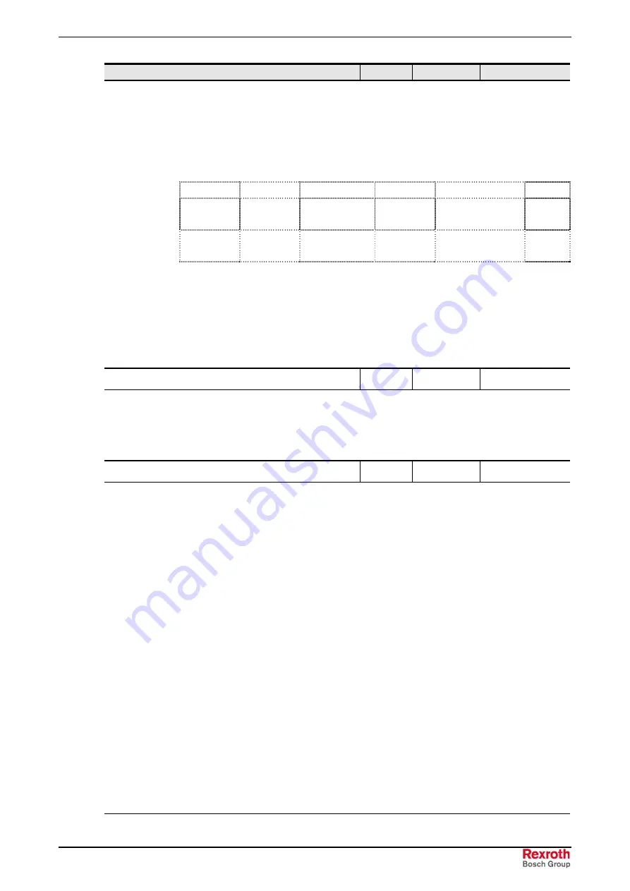
Bit 0
= relay 1
Bit 1
= relay 2
Bit 2
= relay 3 (DOUT1)
Bit 3
= relay 4 (DOUT2)
Bit 4
= Dig AOut 1
(analog output 1)
Bit 5…7
= reserved
Bit 8
= Bus out bit 0
Bit 9
= Bus out bit 1
Bit 10
= Bus out bit 2
Bit 11
= Bus out bit 3
Bit 12
= Bus out bit 4
Bit 13
= Bus out bit 5
Bit 13-12
Bit 11-8
Bit 7-4
Bit 3-0
Min. value
00
0
0000
0
0000
0
0000
0
binary
hex
Max. value
11
3
1111
F
0001
1
1111
F
binary
hex
BUS:
The corresponding hex value is written into the parameter, and thus the relays
and/or digital outputs are set.
Standard control panel:
When the standard control panel is used, directly enter the
hexadecimal code.
Comfort control panel:
Each individual output can be separately called up into the plain
text and activated.
P542
Set analog output
S
0.0 ... 10.0 V
[ 0.0 ]
With this function, the FC's analog output can be set independent of its current operating
status. To this end, the analog output in question must be set to the function "external
control" (P418 = 7).
This function can be used manually or in connection with a bus address. The value set
here is output after confirmation at the analog output.
P543
Actual bus value 1
S
P
In this parameter, the return value 1 can be selected when the bus is addressed.
NOTE:
For more details, please refer to the respective BUS operating instructions or
the description on P400.
0 =
off
1 =
Actual frequency
2 =
actual speed
3 =
Current
4 =
torque current (100% = P112)
5 =
*see status digital inputs & relay
6 =
… 7
reserved
8 =
setpoint frequency
9 =
error Number
10 =
… 11
reserved
12 =
Bus out bit 0…7
13 =
… 16
reserved
17 =
value analog input 1 (P400)
18 =
value analog input 2 (P405)
19 =
setpoint frequency reference
value (P503)
20 =
Setpoint frequency after ramp
reference value
21 =
Actual frequency without slippage
reference value
0 ... 21
[ 1 ]
*see status digital inputs & relay
Bit 0
= DigIn 1
Bit 5
= reserved
Bit 10
= reserved
Bit 1
= DigIn 2
Bit 6
= reserved
Bit 11
= reserved
Bit 2
= DigIn 3
Bit 7
= reserved
Bit 12
= Rel 1
Bit 3
= DigIn 4
Bit 8
= reserved
Bit 13
= Rel 2
Bit 4
= DigIn 5
Bit 9
= reserved
Bit 14
= reserved
Bit 15
= reserved
Summary of Contents for IndraDrive Fc FCS01
Page 28: ...5 2 Delivery Rexroth IndraDrive FCS01 1 DOK INDRV FCS01 IB01_EN P ...
Page 34: ...6 6 Certifications and Types Rexroth IndraDrive FCS01 1 DOK INDRV FCS01 IB01_EN P ...
Page 56: ...8 20 Installation Rexroth IndraDrive FCS01 1 DOK INDRV FCS01 IB01_EN P ...
Page 88: ...10 4 Commissioning Rexroth IndraDrive FCS01 1 DOK INDRV FCS01 IB01_EN P ...
Page 237: ......


