


Rexroth IndraDrive FCS01.1
Parameterization
11-19
DOK-INDRV*--FCS01*****-IB01_EN-P
Parameter
Setting value / description / note
Device
Supervisor
Parameter
record
P401
Mode analog input 1
S
0 =
0 – 10V limited:
An analog setpoint which is smaller than the programmed
adjustment 0% (P402) does not result in reversal of rotation direction.
1 =
0 – 10V:
An analog setpoint which is smaller than the programmed adjustment 0%
(P402) will result in reversal of rotation direction.
In this way, a reversal of rotation
direction can be realized with a simple voltage source and a potentiometer.
e.g. internal setpoint value with reversal of rotation direction:
P402 = 5V, P104 = 0Hz, potentiometer 0–10V
⇒
reversal of rotation direction
will
occur while potentiometer is within the 0 to 5v range.
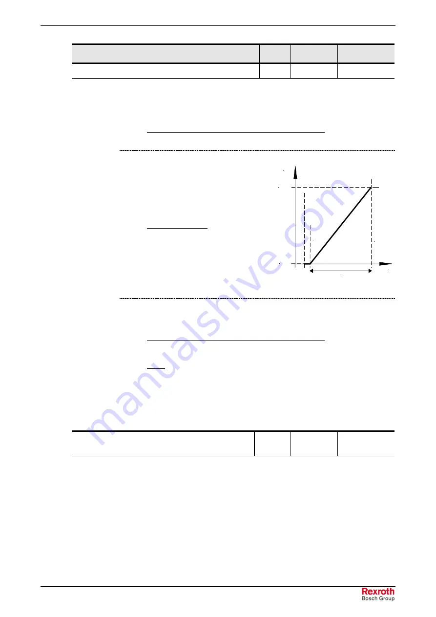
2 =
0 – 10V monitored:
If the value
falls below the minimum adjusted
setpoint value (P402) by 10% of the
difference of P403 and P402, the FC
output will be deactivated. As soon as
the setpoint is higher once more
[
P402 - (10% * (P403 - P402))
], it
will again supply an output signal.
e.g. setpoint 4-20mA:
P402: Adjustment 0% = 2V; P403:
Adjustment 100% = 10V; -10%
corresponds to -0.8V; i.e. 2...10V
(4...20mA) normal operating range,
1.2...2V = minimum frequency
setpoint, the output is switched off if
the value falls below 1.2V (2.4mA).
f/Hz
P104 (fmin)
P105 (fmax)
P
403
=
10
,0
V
P
4
02
=
2,0V
= 8,0V
U/V
O
FF =
2,
0V
-
1
0%
*
8,
0V
=
1,
2V
0 ... 3
[ 0 ]
3 =
- 10V – 10V:
An analog setpoint which is smaller than the programmed
adjustment 0% (P402) will result in reversal of rotation direction.
In this way, a
reversal of rotation direction can be realized with a simple voltage source and a
potentiometer.
e.g. internal setpoint value with reversal of rotation direction:
P402 = 5V, P104 = 0Hz, potentiometer 0–10V
⇒
reversal of rotation direction
will
occur while potentiometer is within the 0 to 5v range.
Note:
At the moment of reversal (hysteresis =
±
P505), the drive will stand still if the
minimum frequency (P104) is smaller than the absolute minimum frequency (P505).
A brake controlled by the FC will not be applied in the range of the hysteresis.
If the minimum frequency (P104) is greater than the absolute minimum frequency
(P505), the drive will reverse on reaching minimum frequency. In the hysteresis
range
±
P104, the FC will supply the minimum frequency (P104), a brake controlled
by the FC will not be applied.
P402:
Adjustment analog input 1
0%
S
-50.00 ...
50.00 V
[ 0.00 ]
This parameter is used to set the voltage corresponding to the minimum value of the
selected function of analog input 1. In factory setting (setpoint), this value corresponds to
the setpoint set via P104 Minimum frequency.
Typical setpoint values and corresponding settings.
0 – 10 V
0.00 V
2 – 10 V
2.00 V (monitored with the function 0-10V)
0 – 20 mA
0.00 V (internal resistance approx. 250
Ω
)
4 – 20 mA
1.00 V (internal resistance approx. 250
Ω
)
Summary of Contents for IndraDrive Fc FCS01
Page 28: ...5 2 Delivery Rexroth IndraDrive FCS01 1 DOK INDRV FCS01 IB01_EN P ...
Page 34: ...6 6 Certifications and Types Rexroth IndraDrive FCS01 1 DOK INDRV FCS01 IB01_EN P ...
Page 56: ...8 20 Installation Rexroth IndraDrive FCS01 1 DOK INDRV FCS01 IB01_EN P ...
Page 88: ...10 4 Commissioning Rexroth IndraDrive FCS01 1 DOK INDRV FCS01 IB01_EN P ...
Page 237: ......


