


2-4
Switching the Target PLC
2-4-2 Procedure
2-33
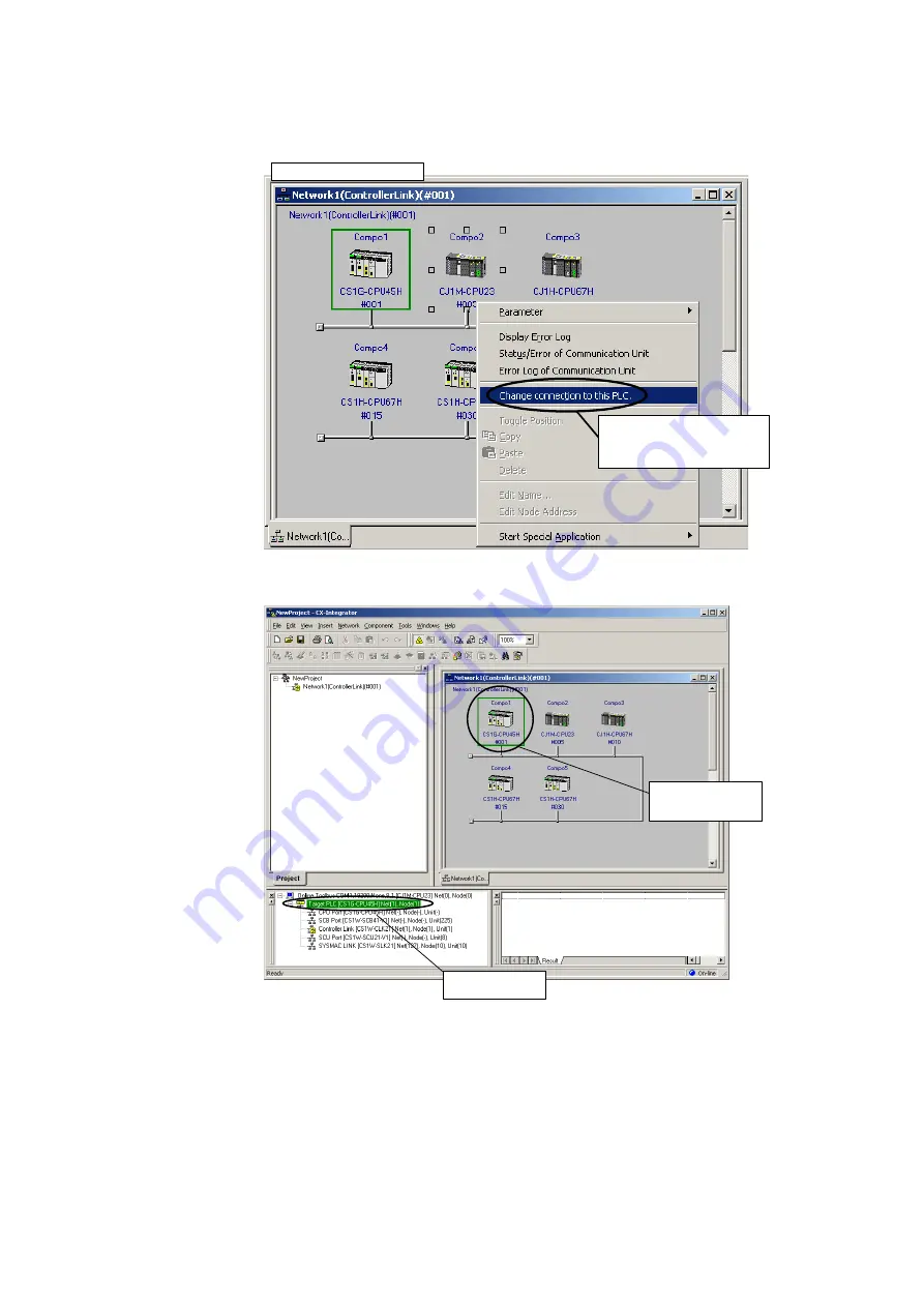
3. Right-click a PLC on the network and select
Connect to this PLC
from the pop-up
menu.
Right-click the PLC for which the
network structure is to be uploaded
and select
Connect to this PLC
from
the pop-up menu.
Network Configuration Window
The selected PLC will be set as the target PLC.
Here, the target PLC is
switched to this PLC.
Example: CS1G-CPU45H
The new target PLC
can be confirmed here.
4. Right-click a Communications Unit/port from the new target PLC and select
Transfer
[Network to PC]
to upload the network configuration.
Summary of Contents for CJ Series
Page 2: ......
Page 3: ...CXONE AL C V3 CXONE AL D V3 CX Integrator Ver 2 3 Operation Manual Revised February 2009 ...
Page 4: ...iv ...
Page 6: ...vi ...
Page 18: ...xviii ...
Page 154: ...Communications Section 3 Routing Tables This section describes how to set the routing tables ...
Page 189: ...3 3 Maintenance after Network Configuration 3 3 2 Editing the FINS Local Network Tables 3 36 ...
Page 244: ...Communications Section 5 Ethernet This section describes the operations specific to Ethernet ...
Page 249: ...5 2 Ping Test 5 2 2 Procedure 5 6 ...
Page 353: ...7 8 Other CompoNet Functions 7 8 2 Installing Expansion Modules 7 32 ...
Page 404: ...Appendices ...
Page 407: ...A 1 CPS File Management A 1 1 Description of CPS Files A 4 ...
Page 413: ......
Page 414: ......
Page 415: ......


