


3-2 Setting the Routing Tables
3-2-5 Transferring Routing Tables to a Directly Connected PLC
3-24
3-2-5
Transferring Routing Tables to a Directly Connected PLC
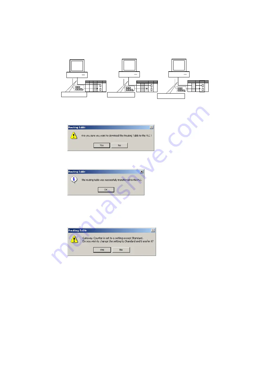
The computers are connected to PLC1, PLC2, and PLC3 by direct serial connections,
and the routing tables are transferred to the PLCs.
Computer (CX-Integrator)
Computer (CX-Integrator)
Computer (CX-Integrator)
Direct serial connection
PLC1 PLC2
PLC3
Direct serial connection
Direct serial connection
Connect with network address
0, and node address 0.
Connect with network address 0,
and node address 0.
Connect with network address 0,
and node address 0.
Connect with network address 0,
and node address 0.
Connect with network address 0,
and node address 0.
1. Verify that PLC1 is connected directly to the CX-Integrator and online, display the
PLC Routing Table Window, and select
Options – Transfer to PLC
.
2. The following dialog box will be displayed to confirm the transfer. To proceed with
the transfer to the PLC, click the
Yes
Button.
3. The routing tables (local network table and relay network table) will be transferred
from the computer (CX-Integrator) to PLC1.
The following dialog box will be displayed after the transfer is completed.
This step completes the transfer of the routing tables to PLC1. Use the procedure
outlined above to transfer the routing tables to PLC2 and PLC3.
Note: The following message will be displayed if a CS/CJ-series Unit with no version number
is being used and the gateway counter was set to
Expand
in the Gateway Counter
Setting Dialog Box.
Click the
Yes
Button to change the gateway counter setting to
Standard
and transfer the
routing tables.
Click the
No
Button to cancel the routing table transfer.
4. After the routing tables have been transferred, update the Online Connection
Information Window by either selecting
Update of Online Information Window
from the View Menu in the Online Connection Information Window or pressing the
F5
Key.
!
Caution
When changing or removing a routing table (see note), be sure to update
the display for the Online Connection Information Window. The display
for the Online Connection Information Window could possibly be different
from the actual network status. If operations are executed without first
updating the display, particularly online operations in the Network
Configuration Window, it could cause data to be mistakenly read or
written for the wrong network or node address or unit number.
Note:
Changing or removing a routing table refers to using the
Summary of Contents for CJ Series
Page 2: ......
Page 3: ...CXONE AL C V3 CXONE AL D V3 CX Integrator Ver 2 3 Operation Manual Revised February 2009 ...
Page 4: ...iv ...
Page 6: ...vi ...
Page 18: ...xviii ...
Page 154: ...Communications Section 3 Routing Tables This section describes how to set the routing tables ...
Page 189: ...3 3 Maintenance after Network Configuration 3 3 2 Editing the FINS Local Network Tables 3 36 ...
Page 244: ...Communications Section 5 Ethernet This section describes the operations specific to Ethernet ...
Page 249: ...5 2 Ping Test 5 2 2 Procedure 5 6 ...
Page 353: ...7 8 Other CompoNet Functions 7 8 2 Installing Expansion Modules 7 32 ...
Page 404: ...Appendices ...
Page 407: ...A 1 CPS File Management A 1 1 Description of CPS Files A 4 ...
Page 413: ......
Page 414: ......
Page 415: ......


