4-3
Manually Setting Data Links
4-3-1
Procedure through Data Link Startup
4-8
4-3
Manually Setting Data Links
Follow the procedure described below to create data link tables manually for Controller
Link or SYSMAC LINK data links.
Note: There is no need to create a data link tables when data links are set automatically. For
details on automatic setup, refer to
Automatically Set Data Links
.
4-3-1
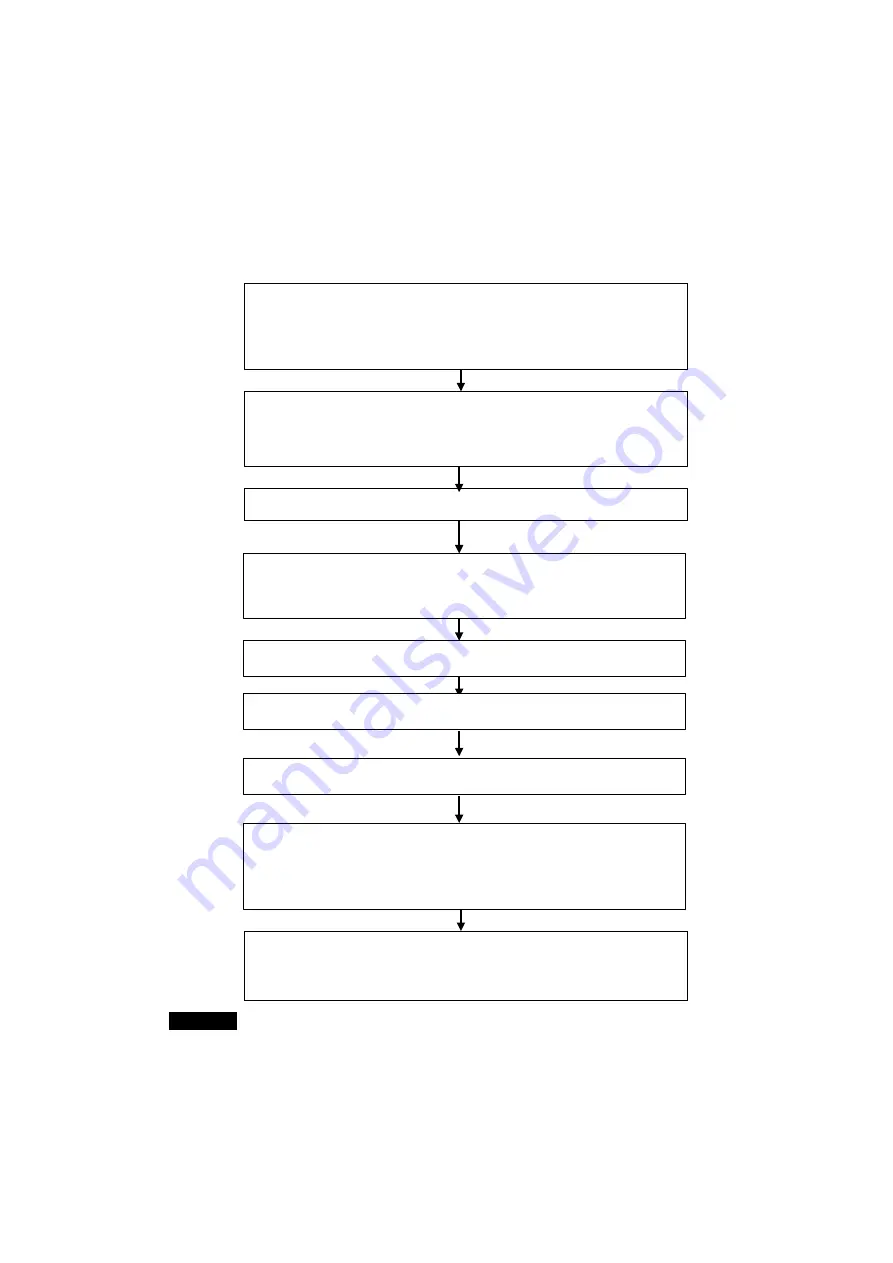
Procedure through Data Link Startup
Read the data link tables that were saved and transfer them to the PLC from the
Data Link Component Window.
1) Right-click the Controller Link Unit or SYSMAC LINK Unit in the CX-Integrator's Online Connection
Information Window, and select
Start DataLink
from the pop-up menu.
2) Select
File - Open
from the Data Link Component Window to read the data link tables.
3) Select
Online - Transfer to PLC
to transfer the data link tables from the computer to the PLC.
Connect the CX-Integrator online to the PLC.
CX-Integrator:
Network - Work Online
(or
Auto Online
)
Save the data link tables.
Datalink Component Window:
File - Save
Check the data link tables.
Datalink Component Window:
Table - Validate Table.
Select the network type.
Select
Controller Link
or
SYSMAC LINK
(not required online).
Create the data link tables offline.
1) Datalink Wizard Settings (
Table - Wizard
). Use the manual setting function if the data link
tables are to be created manually.
2) Node Edit Window Settings
Start the data links from the Data Link Component Window.
1) Select
Online - DataLink Operation/Start.
2) Select the
RUN
Option from the
Operation
Field and click the
Set
Button.
Set the data link type to manual.
Use one of the following methods.
•
Select
Online - Auto Online
and select manually set data links.
•
Make the setting directly in the allocated DM Area words.
Note: This setting can also be made in the Special I/O Unit settings in the CX-Programmer I/O
Table Window.
Start the Data Link Component.
Select
Tool - Start DataLink
offline.
(Alternately, go online, right-click the Controller Link Unit or SYSMAC LINK Unit in the
CX-Integrator's Online Connection Information Window, and select
Start DataLink
from the
pop-up menu.
Reference
Create data link tables manually when any of the following conditions is present:
1. The send area size differs for nodes participating in the data link.
2. The sequence of send nodes differs from the sequence of node addresses.
3. There are nodes that receive only part of the send data (Controller Link only).
4. There are nodes that receive data with an offset specified (Controller Link only).
5. There are nodes that do not send data (Controller Link only).
6. There are nodes that do not receive data.
Summary of Contents for CJ Series
Page 2: ......
Page 3: ...CXONE AL C V3 CXONE AL D V3 CX Integrator Ver 2 3 Operation Manual Revised February 2009 ...
Page 4: ...iv ...
Page 6: ...vi ...
Page 18: ...xviii ...
Page 154: ...Communications Section 3 Routing Tables This section describes how to set the routing tables ...
Page 189: ...3 3 Maintenance after Network Configuration 3 3 2 Editing the FINS Local Network Tables 3 36 ...
Page 244: ...Communications Section 5 Ethernet This section describes the operations specific to Ethernet ...
Page 249: ...5 2 Ping Test 5 2 2 Procedure 5 6 ...
Page 353: ...7 8 Other CompoNet Functions 7 8 2 Installing Expansion Modules 7 32 ...
Page 404: ...Appendices ...
Page 407: ...A 1 CPS File Management A 1 1 Description of CPS Files A 4 ...
Page 413: ......
Page 414: ......
Page 415: ......


