4-3
Manually Setting Data Links
4-3-11 Transferring the Data Link Table
4-40
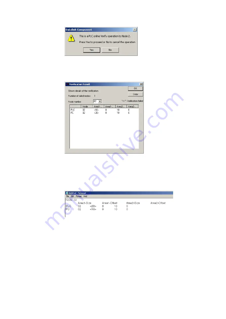
4. Click the
Yes
Button.
A message will appear to tell you if there are any differences between the two sets
of data link table.
5. If differences are found and the
OK
Button is clicked, the Verification Result Dialog
Box will be displayed.
Select the node address to display the data link area data for both the PLC and in
the computer for the specified node address: Area 1 Size, Area 1 Offset, Area 2
Size, and Area 2 Offset. The size of this dialog box can be changed.
The data for the PLC is display on top and that for the computer (i.e., the data being
edited on the CX-Integrator) is displayed on bottom. Inconsistencies are displayed
between pointed brackets < >.
Click the
Copy
Button to place a copy of the verification results on the clipboard for
use in other programs, e.g., text editors, as shown below.
Summary of Contents for CJ Series
Page 2: ......
Page 3: ...CXONE AL C V3 CXONE AL D V3 CX Integrator Ver 2 3 Operation Manual Revised February 2009 ...
Page 4: ...iv ...
Page 6: ...vi ...
Page 18: ...xviii ...
Page 154: ...Communications Section 3 Routing Tables This section describes how to set the routing tables ...
Page 189: ...3 3 Maintenance after Network Configuration 3 3 2 Editing the FINS Local Network Tables 3 36 ...
Page 244: ...Communications Section 5 Ethernet This section describes the operations specific to Ethernet ...
Page 249: ...5 2 Ping Test 5 2 2 Procedure 5 6 ...
Page 353: ...7 8 Other CompoNet Functions 7 8 2 Installing Expansion Modules 7 32 ...
Page 404: ...Appendices ...
Page 407: ...A 1 CPS File Management A 1 1 Description of CPS Files A 4 ...
Page 413: ......
Page 414: ......
Page 415: ......


