


9-2
Transferring Screen Data through the PLC
9-2-2 Procedure
9-7
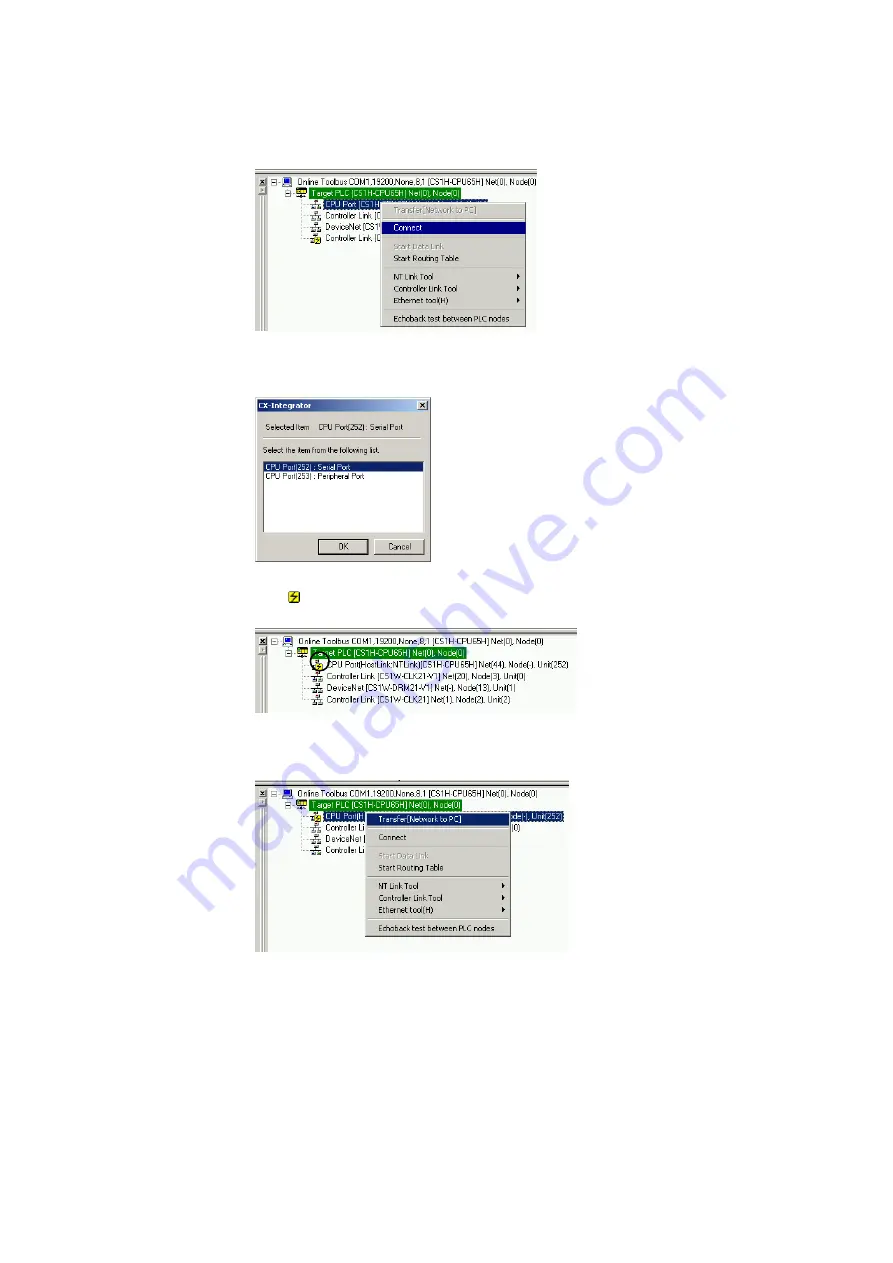
3. The PLC will be connected online to the computer and the PLC’s rack configuration
will be displayed in the Online Information Window.
Right-click the CPU port and select
Connect
from the pop-up menu.
4. A dialog box will be displayed to select the CPU Unit’s serial port.
Select
Serial Port
(the RS-232C port) and click the
OK
Button.
5. The icon will be displayed next to the CPU Unit’s RS-232C port to indicate that
the port can be accessed with NT Link protocol.
6. Right-click the CPU Unit in the Online Information Window and select
Transfer
[Network to PC]
.
7. The following dialog box will be displayed to confirm the transfer.
Click the
Yes
Button to transfer the network configuration of the NT Link network
connected to the CPU Unit’s built-in RS-232C port.
Summary of Contents for CJ Series
Page 2: ......
Page 3: ...CXONE AL C V3 CXONE AL D V3 CX Integrator Ver 2 3 Operation Manual Revised February 2009 ...
Page 4: ...iv ...
Page 6: ...vi ...
Page 18: ...xviii ...
Page 154: ...Communications Section 3 Routing Tables This section describes how to set the routing tables ...
Page 189: ...3 3 Maintenance after Network Configuration 3 3 2 Editing the FINS Local Network Tables 3 36 ...
Page 244: ...Communications Section 5 Ethernet This section describes the operations specific to Ethernet ...
Page 249: ...5 2 Ping Test 5 2 2 Procedure 5 6 ...
Page 353: ...7 8 Other CompoNet Functions 7 8 2 Installing Expansion Modules 7 32 ...
Page 404: ...Appendices ...
Page 407: ...A 1 CPS File Management A 1 1 Description of CPS Files A 4 ...
Page 413: ......
Page 414: ......
Page 415: ......


