


1-5 Window
Descriptions
1-5-2 Main
Window
1-42
Display in
Workspace
Window
Status
Operation
Remarks
Accessible
network
Right-click the network and select
Connect.
Only one network can be accessed at
any one time. Network configurations
can be uploaded or compared only for a
network in this status.
Note: Access is possible to a network
only when it is connected.
Inaccessible
networks
Networks created offline or networks for
which the communications configuration
has been uploaded and then the
connection was changed to a different
network by right-clicking and selecting
Connect
.
Note: Access is not possible to a
network that is not connected.
Network Configuration Window
When the network configuration is uploaded online from the target PLC, the network
configuration will be displayed in this window. If a network is inserted offline, the new
network will be displayed in the Network Configuration Window.
The Network Configuration Window corresponds 1:1 with the Workspace Window.
Online (Same for All Network Types)
The target component’s actual network configuration (including component
parameters) can be uploaded online from the target component by selecting
Transfer
[Network to PC]
after selecting
Connect
. The uploaded network configuration will be
displayed in this Network Configuration Window.
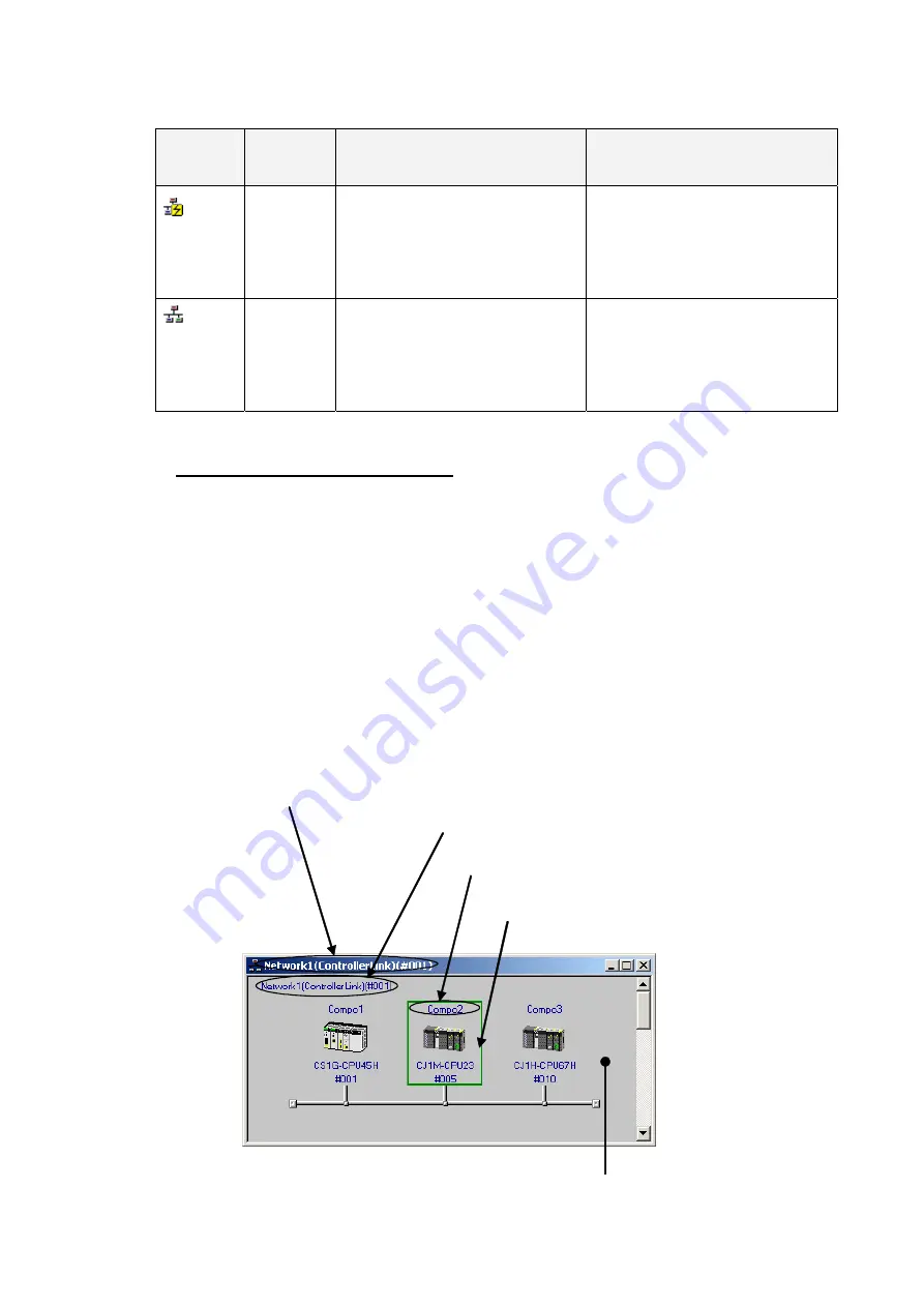
Meaning of Window Background Colors and Target Component Highlighting
The background of the Network Configuration Window will be gray when the window
can be accessed. The target component will be highlighted with a green border.
The window title shows network number (assigned in order starting
with Network1), then the network type, and finally the network
address in parentheses.
The network type is displayed after the network number.
The default component name is “Compo”
followed by a number (assigned in order starting
with 1).
The target PLC is highlighted with a green
border.
The background is gray when online and white when offline.
Summary of Contents for CJ Series
Page 2: ......
Page 3: ...CXONE AL C V3 CXONE AL D V3 CX Integrator Ver 2 3 Operation Manual Revised February 2009 ...
Page 4: ...iv ...
Page 6: ...vi ...
Page 18: ...xviii ...
Page 154: ...Communications Section 3 Routing Tables This section describes how to set the routing tables ...
Page 189: ...3 3 Maintenance after Network Configuration 3 3 2 Editing the FINS Local Network Tables 3 36 ...
Page 244: ...Communications Section 5 Ethernet This section describes the operations specific to Ethernet ...
Page 249: ...5 2 Ping Test 5 2 2 Procedure 5 6 ...
Page 353: ...7 8 Other CompoNet Functions 7 8 2 Installing Expansion Modules 7 32 ...
Page 404: ...Appendices ...
Page 407: ...A 1 CPS File Management A 1 1 Description of CPS Files A 4 ...
Page 413: ......
Page 414: ......
Page 415: ......


