


1-5 Window
Descriptions
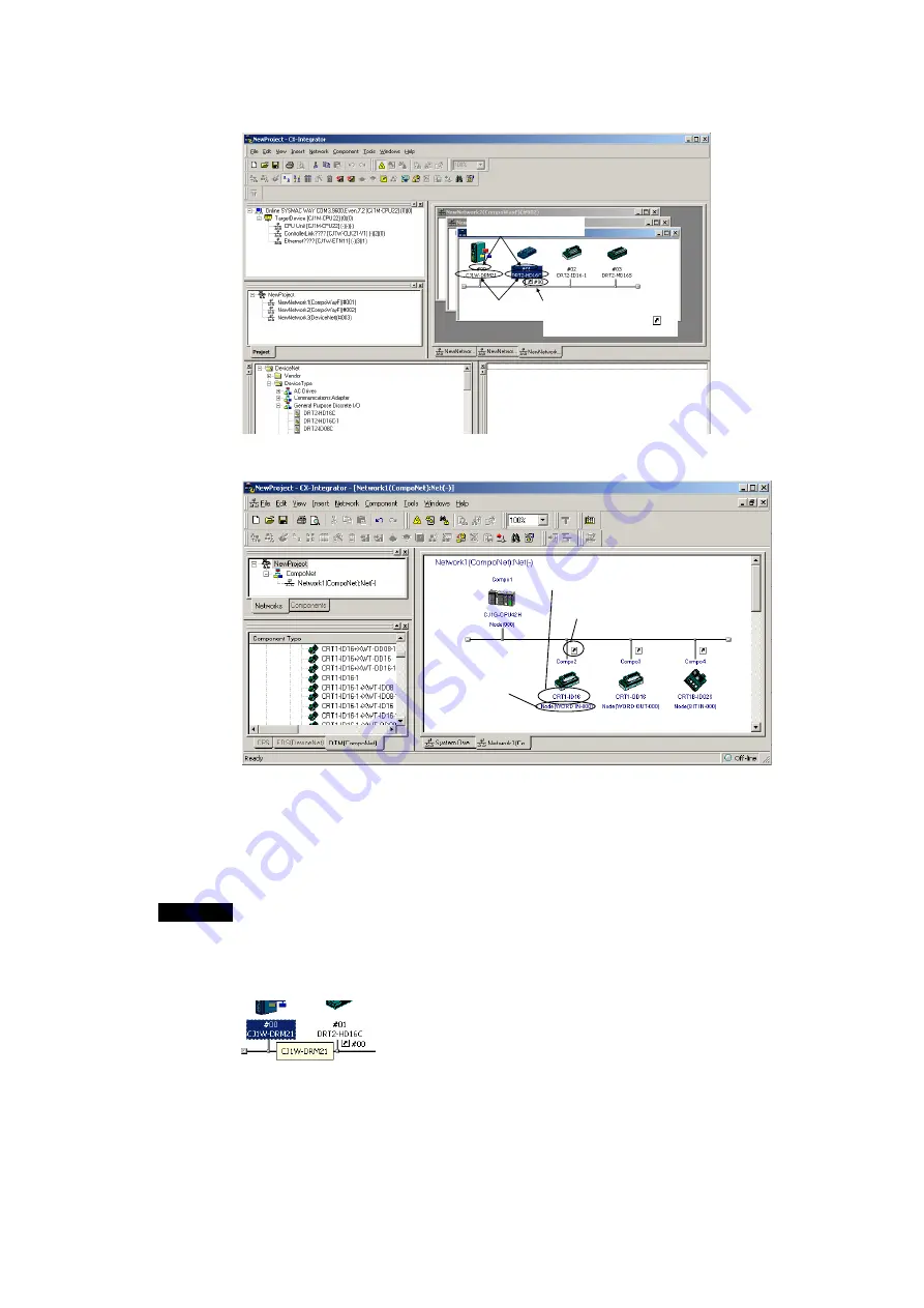
1-5-2 Main
Window
1-44
DeviceNet Example:
Node addresses are displayed
with a # prefix.
Product names
are displayed.
When slaves are registered with the
master, the node address of the
master is displayed after the
icon with a # prefix.
CompoNet Example:
The Unit name is displayed.
The
Arrow
Icon indicates that I/O
allocation has been completed.
The node number for each
slave type (Word IN/OUT,
Bit IN/OUT) is displayed.
Later, the component parameters in the virtual network that was created can be
downloaded to the devices on the actual network online. Furthermore, the
configuration of the virtual network that was created (not including component
parameters) or selected component parameters can be compared to the actual
network configuration or the parameters in the actual component.
Note
The same functions can be performed by right-clicking in the window and selecting
from the Edit or Component Menu. If the mouse pointer is moved to a component, a
description of the component will be displayed in a pop-up.
For networks other than DeviceNet, the version of each component is also displayed
(except for version 0).
Summary of Contents for CJ Series
Page 2: ......
Page 3: ...CXONE AL C V3 CXONE AL D V3 CX Integrator Ver 2 3 Operation Manual Revised February 2009 ...
Page 4: ...iv ...
Page 6: ...vi ...
Page 18: ...xviii ...
Page 154: ...Communications Section 3 Routing Tables This section describes how to set the routing tables ...
Page 189: ...3 3 Maintenance after Network Configuration 3 3 2 Editing the FINS Local Network Tables 3 36 ...
Page 244: ...Communications Section 5 Ethernet This section describes the operations specific to Ethernet ...
Page 249: ...5 2 Ping Test 5 2 2 Procedure 5 6 ...
Page 353: ...7 8 Other CompoNet Functions 7 8 2 Installing Expansion Modules 7 32 ...
Page 404: ...Appendices ...
Page 407: ...A 1 CPS File Management A 1 1 Description of CPS Files A 4 ...
Page 413: ......
Page 414: ......
Page 415: ......


