background image

  2  System Overview

Operator’s Manual

2 - 15

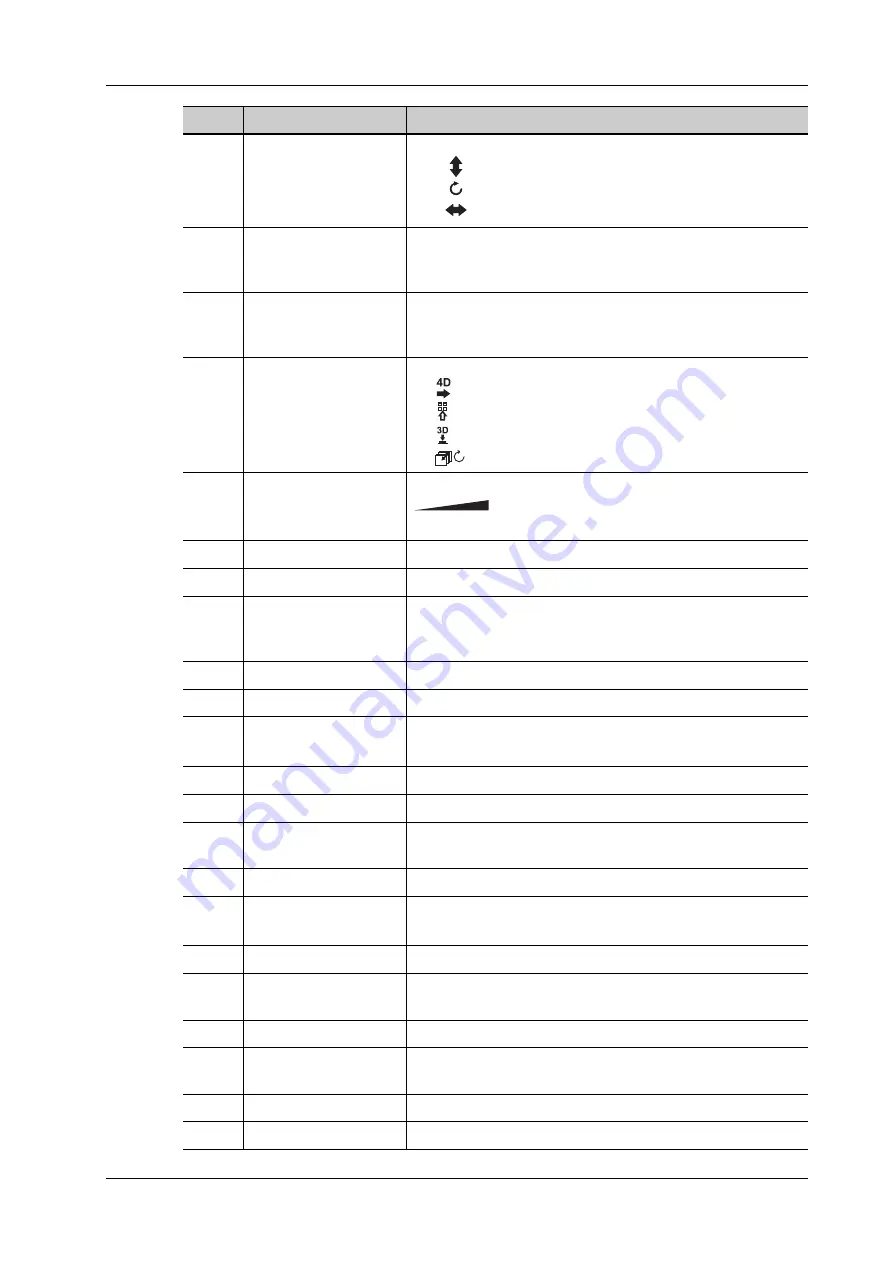
11.

/

• Press: to adjust the angle in increments of 60°.

: Toggle to adjust the Baseline.

: Rotate to adjust the angle.

: Slide to adjust the steer.

12.

PW

Press to enter PW mode, and rotate to adjust PW (in PW 
mode) or CW gain (in CW mode); while in 3D/4D mode, 
rotate the knob to make the 3D image rotate around Y axis.

13.

C

Press to enter Color mode, and rotate to adjust Color (in color 
mode) or Power gain


(in Power mode); while in 3D/4D mode, 

rotate the knob to make the 3D image rotates around Z axis.

14.

/

• Press to enter 3D

: Slide right to enter 4D.

: Slide upwards to enter quad-split display. 

: Slide downwards to enter dual-split display. 

: Rotate to switch the view.

15.

TGC

Slide to adjust the depth gain.

: Indicates the control or indicator to increase or 

decrease a parameter.

16.

Cursor

Display/hide the cursor.

17.

Clear

Remove the comments or measurement caliper.

18.

M

Enter M mode, and rotate to adjust M mode gain. While in 
3D/4D mode, rotate the knob to make the 3D image rotate 
around X-axis.

19.

CW

Enter CW mode.

20.

Power

Enter Power mode.

21.

Dual

Enter Dual mode in Non-Dual mode.
Press to switch between the two interfaces in the Dual mode.

22.

B

Press: to enter B mode; Rotate: to adjust B mode gain.

23.

Depth

Adjust the depth in real-time imaging.

24.

Zoom

Rotate to enter the pan-zoom mode, and press to enter the 
spot-zoom mode.

25.

Measure

Enter/exit the application measurement mode.

26.

Update

Switching key: Press to change the currently active window.
Start/stop image acquisition in iScape or 3D/4D mode.

27.

Caliper

Enter/exit the general measurement mode.

28.

/

Confirm an operation. The function is same with the left-
button of the mouse.

29.

/

Move the trackball to change the cursor position.

30.

/

Confirm an operation. The function is same with the left-
button of the mouse.

31.

iTouch

Press to optimize the images.

32.

Save

Save the image; user-defined key.

No.

Name

Description

Summary of Contents for Imagyn 7

Page 1: ...7OB Resona 7S Resona 7PRO Resona R9 Exp Resona R9 Pro Resona R9S Resona R9 Resona R9W Resona R7W Nuewa R9 Nuewa R9 Exp Nuewa R9 Pro Nuewa R9S Imagyn 7 Nuewa R9W Nuewa R7W Resona Y Diagnostic Ultrasoun...

Page 2: ......

Page 3: ...2 6 System Configuration 2 4 2 6 1 Standard Configuration 2 4 2 6 2 Probes and Needle guided Brackets Available 2 4 2 6 3 Options 2 4 2 6 4 Peripherals Supported 2 8 2 6 5 Parts that can be used with...

Page 4: ...Adapter 3 10 3 8 Connecting Peripheral Devices 3 12 3 8 1 Connecting USB Devices 3 12 3 8 2 Connecting a Footswitch 3 12 3 8 3 Connecting a Graph Text Printer 3 13 3 8 4 Connecting a Video Printer 3...

Page 5: ...ng Setup Data 4 43 4 10 3 Importing Setup Data 4 43 4 10 4 Load Factory 4 43 4 10 5 Probe Check 4 44 4 10 6 Other Settings 4 44 4 11 Security 4 44 4 11 1 Drive Encryption Secure Data Wipe 4 44 4 11 2...

Page 6: ...3 6 8 1 Free Xros M 6 23 6 8 2 Free Xros CM Curved Anatomical M Mode 6 23 6 8 3 Anatomical M Mode Parameters 6 24 6 9 PW CW Mode 6 24 6 9 1 PW CW Mode Image Scanning 6 25 6 9 2 PW CW Mode Image Parame...

Page 7: ...17 3 Manual Examination 6 69 6 17 4 Insert 6 69 6 17 5 Create 6 69 7 3D 4D 7 1 7 1 Overview 7 1 7 1 1 Terms 7 1 7 1 2 ROI and VOI 7 2 7 1 3 About the probes 7 3 7 1 4 MPR 7 3 7 1 5 Free View 7 4 7 1...

Page 8: ...0 7 17 1 Basic Procedures 7 40 7 17 2 Operation Controls 7 41 7 18 Smart Face 7 41 7 18 1 Parameter adjusting 7 41 7 19 Volume CEUS 7 42 7 20 Smart Scene 3D 7 43 8 Elastography 8 1 8 1 Strain Elastogr...

Page 9: ...Mode 11 4 11 3 1 Enter review mode 11 4 11 3 2 Wall Motion Scoring 11 5 11 4 Saving Stress Echo Data 11 6 11 5 Exiting the Stress Echo Feature 11 6 11 6 Measurement and Report 11 6 12 Smart Pelvic Fl...

Page 10: ...es on iStation Review Main screens 15 2 15 1 2 To send images using a shortcut key 15 2 15 1 3 To send images to storage after an exam ends 15 2 15 1 4 Structured Report SR 15 2 15 1 5 Encapsulate PDF...

Page 11: ...Probe Sheath 17 12 17 1 5 Probes Cleaning and Disinfection Sterilization 17 13 17 1 6 Cleaning the probe cable and connector 17 18 17 1 7 Probe Environmental Conditions 17 19 17 1 8 Storage and Transp...

Page 12: ...Up the Reader Take LS2208 as an example A 2 A 1 2 Setting A 2 A 1 3 Scanning in Hand Held Mode A 4 A 1 4 Scanning in Hands Free Mode A 5 A 2 2D Barcode Reader Take DS4308 as an example A 7 A 2 1 Overv...

Page 13: ...re and Accessories F 2 F 2 1 Visual Inspection F 2 F 2 2 Contextual Inspection F 2 F 3 Device Labeling F 2 F 4 Protective Earth Resistance F 2 F 5 Earth Leakage Test F 2 F 6 Enclosure Leakage Test F 3...

Page 14: ...This page intentionally left blank...

Page 15: ...used only for informational or editorial purposes They are the property of their respective owners This posting serves as notice under 35 U S C 287 a for Mindray patents http www mindrayna com patent...

Page 16: ...or damage caused by force majeure such as fire and earthquake Malfunction or damage caused by improper operation or repair by unqualified or unauthorized service people Malfunction of the instrument o...

Page 17: ...tor error or accidents This manual contains warnings regarding foreseeable potential dangers but you shall also be continuously alert to dangers other than those indicated Mindray shall not be liable...

Page 18: ...onsistent with the system or the English manuals refer ONLY to the corresponding English manuals The accompanying manuals may vary depending on the specific system you purchased Please refer to the pa...

Page 19: ...e in which the user and or patient is established These events include device related death and serious injury or illness In addition as part of our Quality Assurance Program SHENZHEN MINDRAY BIO MEDI...

Page 20: ...This page intentionally left blank...

Page 21: ...ctional receptacles are used it may cause the leakage current to exceed the safety requirement In the environment that patient is 1 5 meters around connect peripherals to the auxiliary power outlet or...

Page 22: ...water is sprayed on or into the system electric shock may result or the system may be damaged If water is accidentally sprayed on or into the system contact Mindray Customer Service Department or sale...

Page 23: ...local safety or health regulations concerning the use of keyboards It is not allowed for the operator to have contact with other patients and the electronic parts such as the input output terminal of...

Page 24: ...temperature burns during normal ultrasound examinations It is possible for the surface temperature of the transducer to exceed the body temperature of a patient due to environmental temperature and e...

Page 25: ...otherwise condensation or water droplets may form allowing a short circuit and possible electric shock NOTE DO NOT use the system in the vicinity of strong electromagnetic field such as a transformer...

Page 26: ...t be completed and can become lost or corrupted The iScape feature constructs a single extended image from a series of individual image frames The quality of the final image is user dependent and requ...

Page 27: ...nts compliant with the relevant local regulations Please use the disinfection or sterilization solution recommended in this operator s manual otherwise Mindray will not be liable for damage caused by...

Page 28: ...les and local distribution For CIVCO information please contact the following CIVCO Medical Instruments Tel 1 800 445 6741 www civco com WARNING Allergic reactions in patients sensitive to latex natur...

Page 29: ...B Power PW B Tissue Harmonic Imaging Smart 3D 4D Real time 3D iScape View TDI Color M Strain Elastography Contrast imaging Contrast agent for LVO V Flow STE STQ Contrast imaging Contrast agent for Liv...

Page 30: ...4 1 Power Supply Power input Voltage 220 240 V Frequency 50 60 Hz Power consumption 1000 VA Power output Voltage 220 240 V Frequency 50 60 Hz Power consumption 300 VA note this is the maximum auxilia...

Page 31: ...arm and 23 8 inch monitor Depth 945 10 mm Width 545 10 mm main unit 510 10 mm control panel Height 1390 10 mm with the display vertically stands Weight net weight standard configured but not includin...

Page 32: ...le hook Leak proof cap for the ultrasound gel Cables Operator s Manual 2 6 2 Probes and Needle guided Brackets Available Please see 17 Probes and Biopsy 2 6 3 Options Nuewa R9S Imagyn 7 Nuewa R9W Nuew...

Page 33: ...enerator 2 fusion imaging sensors and 1 trolley for the magnetic generator Fusion imaging should be configured 15 Fusion Control Unit Container Used for carrying the magnetic navigation controller Fus...

Page 34: ...Endocavity STE 49 High frame rate STE STE STE DE FR NA or Endocavity STE should be configured 50 Stress Echo Cardiology Package should be configured 51 Tissue Tracking QA Cardiology Package should be...

Page 35: ...TE STE DE FR NA should be configured 77 DICOM Basic Including Verify SCU SCP task management DICOM storage DICOM print DICOM storage commitment DICOM media storage including DICOM DIR etc 78 DICOM Wor...

Page 36: ...e configured 107 AutoEF Cardiology Package should be configured 108 Smart Pelvic Pelvic Floor Package should be configured 109 R VQS Vascular Package should be configured 110 Smart Hip Pediatrics Pack...

Page 37: ...ces otherwise RF interference may occur and the customer or user must take adequate measures accordingly 2 6 5 Parts that can be used within patient environment Main unit Probes Footswitch Printers 2...

Page 38: ...ight forward by stepping down the right pedal 10 Caster Used for moving the system 11 Input panel Used for connecting ECG leads and USB drive etc 12 DVD Used for DVD reading and writing 13 Monitor sup...

Page 39: ...Used for connecting TV projector ultrasound workstation video capture card etc 3 Network port Used for connecting router ultrasound workstation server etc 4 VGA signal output Used for connecting TV Pr...

Page 40: ...illuminates in green when the power of the batteries is more than 20 It blinks in orange when the power of the batteries is lower than 20 It blinks quickly in orange when the power of the batteries i...

Page 41: ...ule bar code reader printer footswitch DVD recorder etc 2 Microphone input Used for connecting a microphone 3 Used for connecting a pencil probe 4 ECG DC IN Connects to ECG leads to directly obtain th...

Page 42: ...It blinks when reading the disk 2 A power Adjust the acoustic power Indicates the control or indicator to increase or decrease a parameter 3 Volume Adjust the volume 4 Adjust the corresponding functio...

Page 43: ...the comments or measurement caliper 18 M Enter M mode and rotate to adjust M mode gain While in 3D 4D mode rotate the knob to make the 3D image rotate around X axis 19 CW Enter CW mode 20 Power Enter...

Page 44: ...operable item 4 Comment Press to enter or exit the comment status 5 Caps Lock Switch the upper lower case 6 Home Activate the Home function return to start position of the comment 7 Set Home Activate...

Page 45: ...bined keys On the iStation or Review screen use Ctrl and Set to select more than one patient or more than one image Fn key For these combination keys press Fn key to use the functions indicated with a...

Page 46: ...scription 1 System Information Area Displays the manufacturer s logo and product model 2 Patient Information Area Displays the hospital name the exam time patient information the probe model the exam...

Page 47: ...tem Icons Area Displays the relevant system icons such as USB memory device printer network and current system time etc 9 User defined Key Area Displays the functions for the user defined keys see 4 1...

Page 48: ...menu by the trackball and left right Set key 1 Press Cursor to show the cursor 2 Roll the trackball to locate the cursor onto the item to be adjusted For a commanding item or command optional item pre...

Page 49: ...ping mode is unavailable Enter the mapping mode Flip the touch screen from top to bottom area 1 The image on the control screen maps on the touch screen The mapping mode appears Mapping menu operation...

Page 50: ...lso available to access the review page Method 2 Tap the real time image on the touch screen area 3 under mapping mode The tool bar is displayed in real time Tap to enter the preview mode Swipe right...

Page 51: ...a control Tap to select a button to add and tap Confirm Add a user defined control In comment and body mark editing status tap and then tap Custom to bring out the dialogue box for adding user defined...

Page 52: ...lied part Caution AC Alternating current Protective earth ground Pencil probe port Equipotentiality Footswitch Probe socket Reserved used for separate video output VGA input Network port HDMI port Hig...

Page 53: ...number Manufacture date Manufacturer Federal law restricts this device to sale by or on the order of a licensed healthcare practitioner USA Unique Device Identifier Conforms to ANSI Std ES60601 1 IEC...

Page 54: ...This page intentionally left blank...

Page 55: ...tem or using peripherals other than permitted by Mindray make sure the overall leakage current of peripherals and the ultrasound system meets the requirement of the local medical device electrical reg...

Page 56: ...he plug is pulled out accidentally data may be lost 3 2 2 Equipotential Terminal The symbol represents the equipotential terminal that is used for balancing the protective earth potentials between the...

Page 57: ...There is no distortion damage or dirt on the system and peripheral devices If any dirt is found cleaning shall be performed For details see 19 System Maintenance There are no loose screws on the moni...

Page 58: ...n see the current user s information 2 If you want to modify the current password click Change Password 3 Enter both the previous and new passwords and confirm the new password in the dialog box 4 Cli...

Page 59: ...maged If you will not use the system for a long period of time you shall turn off the circuit breaker and disconnect the power to all other peripheral devices To power off your system normally 1 Press...

Page 60: ...the standby status and you need to power off Press the power button to exit the standby status and then power off the system 3 4 Adjusting Monitor Position Gently hold the bottom edge of the monitor...

Page 61: ...ilted 20 backward and can be tilted forward to a horizontal position When transporting or moving the system keep the monitor in the horizontal position as shown below 3 4 4 Locking the Monitor If the...

Page 62: ...p and then select System General Brightness auto adjustment The system will automatically adjust the brightness contrast ratio of the main screen and touch screen according to the surrounding environm...

Page 63: ...amaging the cable Only use the probes provided by Mindray Aftermarket probes may result in damage or cause a fire 3 7 1 Connecting a Probe WARNING The probes cables and connectors should be in proper...

Page 64: ...ver 90 counterclockwise to the horizontal position 2 Pull the probe connector straight out vertically 3 7 3 Installing a Probe Adapter Figure 3 1 Probe Adapter Illustration NO Description 1 Probe sock...

Page 65: ...ion Then push probe adapter to probe port slowly and carefully while keeping the socket position upward 2 Rotate the probe adapter locking lever 90 clockwise to the vertical position to lock it 3 Stic...

Page 66: ...To remove the USB device click to open the Remove USB Device screen Select the device to be removed and click OK A sound is heard when removing the USB memory device The diagnostic ultrasound system...

Page 67: ...Setup Print Add Printer All the operations are finished with right Set button 5 Select The printer that I want isn t listed 6 Select Add a local printer or network printer with manual settings and cl...

Page 68: ...screen and set the items in the Property box 3 Click Save after you have finished setting 3 8 4 Connecting a Video Printer NOTE Unless otherwise specified printers listed in Chapter 2 6 4 Peripherals...

Page 69: ...V Flow S Planes by factory default It is designed for replacing the rectangle caps by the user Insert the paper clip or pen into the slot around the rectangle buttons P1 P2 P3 iWorks Fusion Elasto Con...

Page 70: ...g of the tray align with the center of the control panel base and make the upper edges of the tray lap on the control panel base Storage Tray of Main Unit Top Cover Hold the two sides of the storage t...

Page 71: ...3 System Preparation Operator s Manual 3 17 NO Description 1 Main unit top cover storage tray 2 Base arm 3 Turbine protective cover 2 3 1...

Page 72: ...This page intentionally left blank...

Page 73: ...shuts down to make the modification effective Basic operations The commonly used setting types are Text box position the cursor over the corresponding field box Enter the desired value using the keyb...

Page 74: ...Description Item Description HOSPITAL INFORMAT ION To set the hospital relevant information such as name address telephone and so on Load Logo Import image for logo loading NOTE For a better display...

Page 75: ...exam data to the DICOM server for storage print Sending SR After Ending Exams Select whether to automatically send structure report to the DICOM server Save Patient Info Dialog After Ending Exams Sele...

Page 76: ...h screen according to the conditions LCD To set the brightness and the contrast of the main screen or restore to the default TouchPanel After selection the system restores the touch screen settings ba...

Page 77: ...iScape ruler in iScape imaging mode B Color Refresh With PW CW Sampling Line Movement To set whether to turn on the function that when moving PW CW sampling line B Color image is activated under B Co...

Page 78: ...er of cardiac cycles in the heart rate calculation In heart rate measurement the number of cardiac cycles should match the preset number Ellipse s style To set the style of ellipse calipers Trace line...

Page 79: ...y the SD or EDD in the obstetric result On the Fetal Gestational Age page select whether to display the EFW derived GA in the report To set the fetal weight display Perform the following procedure 1 E...

Page 80: ...alue Minimum value Measurement value Maximum value enter the number of days without the unit Table Type Author Name SD Type Meas Value Unit SD Unit FG The author name Value of standard deviation Unit...

Page 81: ...g to 41 weeks after checking EDD LMP 287 41 weeks Display EFW GA in Report Estimate GA according to EFW data after checking Reference Value Range You can select whether to display obstetrics reference...

Page 82: ...etting You can assign a function to the left middle right key of the foot switch The method is similar to setting key functions Other Settings 4 1 7 Gesture The gesture setting is the same with the se...

Page 83: ...trator Type Item Description Send To BMP TIFF JPG To set the image parameters when sending to other locations AVI MP4 WMV DCM DICOMDIR Digital Output Size Output Size To select the VGA HDMI output siz...

Page 84: ...Deleting a User Turn on the access control function and log in to the system as Administrator before you delete the user Select the user to be deleted in the User List Click Delete to delete the selec...

Page 85: ...is locked Reset all lockout Reset all locked accounts Enable strong password The password length must be 6 64 Enable strong password to improve security If the strong password is enabled and you log i...

Page 86: ...ed and click Delete Modifying the member name or privileges Select a member to be modified modify the member name and select or deselect privileges from the drop down list of Privilege Click Modify an...

Page 87: ...of Patient ID Other ID First Name Last Name Middle Name Birth Day Birth Month Birth Year Age Gender and etc in the Content list Note Ignore item is used to add one line below the selected item to hide...

Page 88: ...data of the scanned barcode will be displayed in the corresponding selected default item For example if the default item is set to Patient ID and both the 2D and 1D barcodes fail to be matched the ob...

Page 89: ...m modes On the left side you can view all the available exam modes in the exam library for the probe On the right side of the screen you can view the current exam modes assigned to the probe Click add...

Page 90: ...ific clinical application which are indicated by in the preset screen For example AFI in the OB measurement Fold unfold the study to hide show the measurement or calculation items included On the touc...

Page 91: ...ing 7 Select the measurement sequence Item Description Item Name Results obtained from D Trace are listed The selected items will be displayed in the results window after measurement If PV is selected...

Page 92: ...e in the measuring status Package editing includes Creating Packages Add Remove Items Deleting Measurement Packages Setting Default Packages Adjusting Package Positions Creating Packages Click New and...

Page 93: ...rocedure 1 Select the Measure tab page 2 Click New The Measurement Custom Wizard dialog box appears 3 Enter the Name in the Measurement Custom Wizard dialog box select Add Meas then select Next 4 Sele...

Page 94: ...operations in which the parameters are measurement calculation or study results obtained in measurement items which exist in the system or are user defined Perform the following procedure 1 Select the...

Page 95: ...tributes in the dialog box are shown in the following table Attributes Descriptions Formula Displays the user defined formula Verify Used to verify if the formula is valid App Region Select the applic...

Page 96: ...an be added to the formula Unit Used to enter numbers and functions in the formula Function Method Number of Parameters Function Description sin sin a 1 Sine the ratio of the opposite to the hypotenus...

Page 97: ...the item to the user defined study 6 Repeat the step 5 to add more items if necessary 7 Move the cursor to click on the study and click Property on the right to edit the measure sequence Edit User def...

Page 98: ...Measurement Calculate Study or All from the drop down list beside Available Items The corresponding items appear in the list c Use the or buttons to add items to the Selected list Only tools which app...

Page 99: ...from the list 3 Click Delete Yes to delete the selected template 4 Click Save to confirm the settings Editing Report Templates Perform the following procedure 1 Select the Report on the Measure page 2...

Page 100: ...scriptions Standard Item Provides a set of default measurement items and sets relevant parameters 1 Select a measurement item from the drop down list and set the grade segment The unit is provided by...

Page 101: ...d Items on the right Change position of the selected items Select an item on the right side box and click Up Down Left or Right button to change the position of the item Withdraw or delete a user defi...

Page 102: ...otocol in the list on the left and click Copy A protocol named XXX_Copy1 is created with the copied views which can be customized Select a view with Left Lt Right or Rt in its name in the list on the...

Page 103: ...alog box 2 Enter the protocol name in the Protocol Name box at the top 3 For each view all views display for each phase a Select New View in the View list b Select a standard view from the Standard Vi...

Page 104: ...Machine then in the figure above the AE Title of Local should be Machine and the AE Title of storage server should be Storage The device name is random If the server name is same with that in the DICO...

Page 105: ...S Port Set the TLS port TLS Server Setting Import the encryption key certificate TLS Client Setting After importing TLS certificates and selecting Verify Certificate check box the system verifies the...

Page 106: ...y from the Strategy Items List reselect the function or re enter the parameter 1 2 and click Update 4 Import Export strategy Import Click Import browse the desired strategy file and operate according...

Page 107: ...ult Here the port should be consistent with that of the storage server port Maximum Retries Set the maximum retries 0 9 The default value is 3 If the DICOM task sending to the server fails the retry t...

Page 108: ...et the transfer mode for the 3D 4D cine sending Normal use the way that 2D image adopts to send Volume use Enhanced US Volume Storage IOD to send Data source used to obtain 3D 4D image for 4D Viewer S...

Page 109: ...ng Please select the type the printer supports Film Orientation Select between LANDSCAPE and PORTRAIT Priority Specify printing task priority among HIGH MED and LOW Film Size Select film size among th...

Page 110: ...n to the service TLS Transport Layer Security Select whether to encrypt the data during network transportation Strategy Name Set the DICOM strategy Remove Attribute Set what DICOM element s that will...

Page 111: ...aximum Retries Reserved feature Interval Time Sec Reserved feature Timeout Sec Refers to the amount of time after which the system will stop trying to establish a connection to the service Associated...

Page 112: ...terval Time Sec Reserved feature Timeout Sec Refers to the amount of time after which the system will stop trying to establish a connection to the service Listen Mode This function enables the ultraso...

Page 113: ...o be updated in the service list 2 You can see properties in the Configure Service area 3 Modify the parameters and click Update to update the setting Advance Enters the VPN Advance Config interface R...

Page 114: ...lowing procedure 1 Select Remote Maintenance Permission 2 Select Upload logs to remote server to upload logs to the remote server Mindray service engineers can acquire and handle those log 4 8 4 Q Pat...

Page 115: ...sentative for details 4 10 2 Exporting Setup Data This function is used to write all setup data of the system into a disk for backup The format of the data file is PDP You can select 2 types of preset...

Page 116: ...ve Encryption Secure Data Wipe Encrypt the patient data stored in the hard disk The system provides two encryption methods Factory Default and User Define Factory Default the system is in factory stat...

Page 117: ...s an option If the McAfee software is installed the system displays McAfee is running If you want to buy McAfee contact Mindray representatives NOTE McAfee cannot be uninstalled after successful insta...

Page 118: ...This page intentionally left blank...

Page 119: ...a new patient exam it is better to type the detailed patient information The system will set up a unique information database for each patient based on the patient information entered so that the inf...

Page 120: ...People who is responsible for the exam Operator People who is responsible for images collection and scanning Ref Physician People who requires the operator to do the ultrasound operation Exam specifi...

Page 121: ...ate the GA and EDD BBT input BBT the system will calculate the GA and EDD EDD after you enter EDD the system will calculate and display GA and LMP IVF After you enter IVF the system will calculate GA...

Page 122: ...on from the system hardware or USB memory device You can enter the searching conditions for the patient 1 Do one of the following to enter iStation screen Press F2 iStation on the control panel Click...

Page 123: ...des The recently used probes and exam modes are displayed on the left side of the touch screen Select an appropriate probe and exam mode for quick switch IP Image Process switch For the application th...

Page 124: ...rent probe 5 Press the user defined key to switch the images of two probes 5 2 2 Bi plane Probe Switch For the probe ELC13 4U after selecting the exam mode enter B mode and tap C or L on the touch scr...

Page 125: ...status turns paused after the system restart When an exam is paused the system will Save the exam related images reports and measurement data modify the status as Paused Save the exam information inc...

Page 126: ...This page intentionally left blank...

Page 127: ...t results of the merged image may be inaccurate Therefore the results are provided for reference only not for confirming a diagnosis 6 1 Imaging Mode Switching Between Image Modes Refer to 2 11 Contro...

Page 128: ...for the parameter with icon tap to display the submenu to select the desired value Functional item tap to go to the corresponding function 4 Knob adjusting area Displays the knob controlled parameter...

Page 129: ...obe Click Advanced The value to TIC TIB TIS can be set Click Advanced and then enable Sampling Line Displaying The sampling line always appears after being set when entering PW M TVM mode for once Pre...

Page 130: ...djust the gain of the whole receiving information in B mode The real time gain value is displayed in the image parameter area Depth This function is used to adjust the display depth of sampling the re...

Page 131: ...Line Density The function determines the quality and information of the image Dynamic Range Dyn Ra Adjusts contrast resolution of an image compresses or expands gray display range Smooth This feature...

Page 132: ...he ROI is clearer than these outside when the function is enabled TIP The function is disabled in frozen state iTouch To optimize image parameters as per the current tissue characteristics for a bette...

Page 133: ...Pelvic Floor exam mode Dehaze This function can restrain noise so as to enhance the contrast resolution of the image V 1 1 This function is to display images in vertical format in the dual split mode...

Page 134: ...screen displays the real time parameter values as follows ROI Adjustment To adjust the width and position of ROI in Color mode When the ROI box is solid line roll the trackball to change its position...

Page 135: ...more sensitive indication for low velocity flow becomes It affects the frame Flow State Refers to optimizing the various flow states Persistence This function is to adjust the temporal smooth to optim...

Page 136: ...range and marking position iTouch To optimize image parameters as per the current tissue characteristics for a better image effect HR Flow Enhance tiny vessel display to analyze the blood supply of th...

Page 137: ...the color flow energy signal TIP This parameter is only applicable to sUMA 6 4 Power Mode Power mode provides a non directionally display of blood flow in the form of intensity as opposed to flow velo...

Page 138: ...s to adjust the transformation of echo intensity into color signal Increasing dynamic range will lead to higher sensitivity to low power signals thus enhances the range of signals to display 6 5 V Flo...

Page 139: ...the real time B Color mode adjust the probe and the image to locate the desired region at the center of the B Color mode image 2 Tap V Flow or user defined key to enter V Flow mode Roll the trackball...

Page 140: ...ch indicates the display effect of color image The blood flow information is displayed via switching among the different spectrums The color of the arrow changes after completing the adjustment Gain U...

Page 141: ...nger with the value becoming larger Arrow Size The end point of the arrow does not change with the value becoming larger but the arrow length becomes longer The end point of the arrow does not change...

Page 142: ...white arrow indicates the speed direction of the cursor Move the cursor to any position of the blood vessel the single speed time curve and the vector graphics are updated in real time click Velocity...

Page 143: ...speed of the current frame maximum speed of all the frames during T1 T2 time average speed of the current frame average speed of all the frames during T1 T2 time median speed of the current frame blo...

Page 144: ...lt by pressing Update to activate it and press Clear 6 5 4 Volume Flow Calculation Perform the following procedure 1 Capture image as described in steps 1 5 see 6 5 1 Basic Operations 2 Roll the track...

Page 145: ...ired you can delete the result by pressing Update to activate it and press Clear 6 5 5 WSS Wall Shear Stress Perform the following procedure 1 Capture image as described in steps 1 5 see 6 5 1 Basic O...

Page 146: ...he indices value Tap Blood Viscosity to change Wall shear stress indices Delete wall shear stress point After 3 stress points are added you can delete the point by pressing Update to activate it and p...

Page 147: ...area on the right side of the screen displays the real time parameter values as follows Gain To adjust the gain of M mode image the real time gain value is displayed in the image parameter area Increa...

Page 148: ...press C In B Color press M 2 To enter Color Tissue M mode Press TDI or tap TDI on the touch screen and then press M or Update In B TVI TVD or B TVI TVD mode press M 3 Adjust the image parameters to o...

Page 149: ...nter Free Xros M mode There are 3 M mark lines available each with a symbol of A B or C at one end as identification 3 Adjust the sampling line single line or couple of lines to obtain optimized image...

Page 150: ...ith a number in sequence 7 Repeat Step 6 to finish the sampling line Double press Set to finish the editing 8 You can edit the curve if needed a After finishing the sampling line tap Edit on the touch...

Page 151: ...the trackball left and right Set the SVD by moving the trackball up and down and adjust the angle and SV size according to the actual situation 3 Press PW CW again or Update to enter PW CW Mode and pe...

Page 152: ...er mode of the probe the real time value of which is displayed in the image parameter area Scale This function is used to adjust the speed range of color flow which is adjusted through PRF in the syst...

Page 153: ...n the image parameter area Tint Map This function provides an imaging process based on color difference rather than gray distinction Gray Map Selects among post processing map curves to optimize grays...

Page 154: ...mation of low velocity and high amplitude tissue motion specifically for cardiac movement There are 4 types of TDI mode available Tissue Velocity Imaging TVI This imaging mode is used to detect tissue...

Page 155: ...nel to return to B mode 6 10 2 TDI Mode Image Parameters In TDI mode scan the image parameter area in the right corner of the screen will show the real time parameter values as follows TVI TEI TVD TVM...

Page 156: ...rve Strain Deformation and displacement of the tissue within the specified time Strain rate speed of the deformation as myocardial variability will result in velocity gradient strain rate is used comm...

Page 157: ...Width Angle When selecting Ellipse ROI Press Set to confirm the start point and use the trackball and press Set to confirm the next point then use the trackball to adjust the size and press Set to co...

Page 158: ...mage Analysis curve data Analysis parameter 7 Tap Exit to exit the quantitative analysis 6 11 iScape View The iScape panoramic imaging feature extends your field of view by piecing together multiple B...

Page 159: ...capture preparation status tap B Power Color page tab to go for the B mode image optimization Do measurement or add comment bodymark to the image if needed 4 Tap Start Capture or press Update on the c...

Page 160: ...Map on the touch screen to select the map as in Power mode Image Zooming Rotate Zoom to zoom in or zoom out the image Rotate the button clockwise to zoom in the image the max factor is 10 Rotate the b...

Page 161: ...auto play mode the review region is confined to the set start point and end point Tap iScape Overview to exit cine review mode The panoramic image displays In cine review mode press Freeze on the con...

Page 162: ...djust parameters Speed Adjust refresh speed of vessel wall motion curve Position Adjust the location of the motion curve upwards and downwards Curve Disp Min Curve Disp Max Adjust amplitude of vessel...

Page 163: ...to locate ROI over the target area The dotted line of the ROI is in the middle of the blood vessel Press Set to confirm the position and size of the ROI 4 Tap Start Calc to measure RIMT of left caroti...

Page 164: ...image Use Cycle to select and find the image of interest 3 Select the corresponding section name and locate one frame image with good image effect by cine play Use the cursor to set the reference poin...

Page 165: ...of AVO aortic valve open AVC aortic valve close MVO mitral valve open MVC mitral valve close 3 Display curve Velocity Displacement Strain Strain Rate Each curve on the image is matched with a certain...

Page 166: ...e curve and if you press Set at this time the frame marker will move to the spot The segment boundary color indicates the tracking quality 6 Displays measurement and calculation results EDV Maximum va...

Page 167: ...ally after trace is finished press Set twice to finish tracing NOTE At least 6 points should be determined by you before the system generates automated trace Press Set to make the traces on the image...

Page 168: ...ng points on the epicardium Track Point adjusts the number of points within the segment Cycle select the next cycle Display Effect turns on off the arrow vector graphical display of the myocardial mov...

Page 169: ...hort axis sections of PSAX AP and PSAX B Torsion is acquired by calculating difference of apex and base of the heart Torsion PSAX AP Rot PSA XB Rot The X axis represents time s The Y axis represents t...

Page 170: ...age on account of the magnetic spatial navigation function Lesion Viewing and Marking to show the lesions marked on the ultrasonic planes the ultrasound image and CT MR PET freehand image are displaye...

Page 171: ...elow 1 Auxiliary output power supply cable 2 USB Data cable 3 Magnetic generator 4 Positioning probe sensor port 5 Motion abdomen sensor port 6 Sensor 2 7 Positioning probe navigation support 8 Motion...

Page 172: ...end to the USB port of the Ultrasound System 3 Magnetic generator Transmitter port Plug the magnetic generator to the Transmitter port Place it around the patient s shoulder or two sides of the patie...

Page 173: ...lastic markers on the probe 1 in the figure and on the positioning probe navigation support 2 in the figure must be on the same side The silk prints on the probe 1 in the figure and the navigation sup...

Page 174: ...robe navigation support are installed 5 Motion abdomen sensor fix the motion abdomen sensor which is already plugged in motion abdomen sensor port to the cavity of the motion abdomen sensor support fo...

Page 175: ...or 2 Magnetic generator 3 Magnetic navigator 1 2 3 No Image Description 1 Ultrasound Display When Fusion Ratio is among 1 to 0 the Ultrasound System registers CT MR PET freehand image to ultrasound im...

Page 176: ...ndicator is on positioning probe sensor and 2nd indicator is on motion abdomen sensor 3rd indicator is on Needle Navigation Guiding sensor 4th indicator are reserved functions Check the indicator beco...

Page 177: ...nt for any circumstances after the freehand volume data is imported or acquired Otherwise the registration display for freehand image and the ultrasound image is affected 5 The brightness and the grey...

Page 178: ...mage and CT MR PET freehand image Synchronous display effect The Ultrasound System represents the ultrasound image and CT MR PET freehand image synchronously after the ultrasound image and CT MR PET f...

Page 179: ...the image See XX 12 Conduct the ultrasonic exam and operation after the registration is completed 13 Freeze the ultrasound image to save the single frame image or multi frame cine Contrast Fusion Imag...

Page 180: ...alignment tissue plane The liver enveloped in CT MR PET freehand volume data The registration effect will be better if the CT MR PET volume data already bears the data of Contrast Imaging with the ul...

Page 181: ...ta or backup file of the Ultrasound patient data is in the root directory of USB disk portable hard disk optical disk the Ultrasound System does not pop up the path However volume data or patient data...

Page 182: ...n lesion position on CT MR PET Freehand image Be sure of the lesion appearing on US and CT MR PET Freehand image at the same time after the registration is completed TIP Mark the tumor or lesion on CT...

Page 183: ...lesion with the circle Double press Set to complete adding the mark Manual tracing roll the trackball to manually envelop the lesion Rotate the 4D key to scroll the CT MR PET Freehand image and conti...

Page 184: ...the result window 3 Click Esc to exit Enter Fusion Imaging page Move the probe to view the mark situation in varied planes The mark in the following figure is enveloped with three circles There are r...

Page 185: ...m the result window the cross appearing in the circle Tap Delete Cur to remove the tumor mark Tap Delete All to remove all tumor marks NOTE The button Clear is disabled when tumor mark is activated Di...

Page 186: ...respiration curve Respiration Curve Description 3 Tap Set Modeling ROI to highlight it it is activated by default Move the trackball to set ROI position and size Set ROI position and size Envelope the...

Page 187: ...remium motion modeling Conduct step 3 4 repeatedly based on your demands Set motion modeling repeatedly until a premium one appears 5 Tap Motion Compen to activate it Move the probe The Ultrasound Sys...

Page 188: ...images using linear scan or rocked scan Linear scanning Move the probe across the surface slowly at a constant speed Rocked scanning Rotate the probe once from the left to the right side or from the...

Page 189: ...ide and 0 only relates to ultrasound image on the left window side Image Magnification The lesion or tumor ultrasound and CT MR PET freehand image becomes clearer and easier to register via Zoom key R...

Page 190: ...nder the Tint Map item on the touch screen to select the map The system provides 8 different color effect maps Press the knob under the Tint Map item on the touch screen to turn on off the function Si...

Page 191: ...ET Freehand image on the Ultrasound System and obtain a desired CT MR PET Freehand plane to register Rotate the 4D key clockwise The transverse plane moves towards the patient s head The R L axis and...

Page 192: ...the screen If necessary tap Smart FHR Cycle to set the number of heart rate cycle and the measurement result is updated simultaneously 6 16 1 iPage Operation Procedures Perform the following procedure...

Page 193: ...red Spacing The value is displayed at the upper right side of the slice unit mm Adjust it through touch screen selection Spacing 6 17 iWorks Auto Workflow Protocol The main objective of ultrasound wo...

Page 194: ...Prev Next to select the view to be scanned The current view is surrounded by a solid frame View Operation In the current active view you can perform image scanning measurements and adding comments an...

Page 195: ...following procedure 1 Tap Insert on the touch screen to enter the status 2 Select the necessary protocol and the system adds the protocol events to the current protocol 3 Perform measurements or add...

Page 196: ...This page intentionally left blank...

Page 197: ...bservation 7 1 1 Terms Volume data to obtain the data collection of three dimensional object via the sequence reconstruction to two dimensional object 3D image Volume Rendering VR the 3D image on the...

Page 198: ...ustment change the curved shape of the nearest VOI section front section to facilitate observation for the interested volume data It can be adjusted both in acquisition preparation status and in A B C...

Page 199: ...ic 3D imaging 4D imaging iPage SCV CMPR Color 3D or Niche a volume probe should be selected 7 1 4 MPR MPR represents three different views of 3D image In the quad display format view the screen displa...

Page 200: ...easily found without any actual probe position and direction change It not only reduces the operations but most importantly it decreases the discomfort of patients resulted from probe moving When the...

Page 201: ...an example the other parts imaging are same as 3D 4D imaging NOTE In accordance with the ALARA As Low As Reasonably Achievable principle please try to short the sweeping time after a good 3D imaging i...

Page 202: ...e to ensure High contrast between the desired region and the amniotic fluid surrounded Clear boundary of the desired region Low noise of the amniotic fluid area Scanning technique only for Smart 3D St...

Page 203: ...scanning 2 Obtain a 2D image and optimize the image if necessary 3 Press to enter Static 3D mode and define the ROI and curved VOI Methods to adjust the ROI Under acquisition preparation status Roll...

Page 204: ...VOI setting parameter adjustment comments image saving image cutting etc For details please see 7 3 3 Static 3D Image Viewing 6 Exit static 3D Press B or press to exit Static 3D mode It returns to B m...

Page 205: ...Max Set Max as 3D image rendering mode displays the maximum echo intensity in the observation direction This is helpful for viewing bony structures Min Set Min as 3D image rendering mode displays the...

Page 206: ...indows is orange as well Positions of the other two sectional planes are indicated in the selected plane You can roll the track ball to change the position MPR Only Tap on the touch screen to display...

Page 207: ...or VR c Roll the trackball to adjust VOI position size and curved VOI and press Set to toggle among the adjusting status or you can rotate 4D knob on the control panel to adjust section image positio...

Page 208: ...ho which will contribute to a clearer and smoother image Available only in Surface rendering mode Opacity To adjust the transparency value for 3D image rendering It implies the transparency of the lig...

Page 209: ...r to optimize VR image Select MPR image Adjust 3D iClear to optimize MPR image Face Optimize the signal of the face area to reduce the noise of the AF area and improve the signal noise ratio of the fa...

Page 210: ...state 2 Select Left Right or Up Down to set the auto rotation direction 3 Select the angle under rotation range to set the auto rotation range 4 Set Start position and End position Start position rol...

Page 211: ...et twice to finish tracing Move the cursor to the region you want to edit and press Set again to edit Contour Press Set to position the start point roll the trackball to trace the region When the star...

Page 212: ...seases 7 4 1 Basic Procedures for Color 3D 1 Enter into color 3D image acquisition preparation status a Obtain a feasible Power Color image with the volume probe b Press knob to enter 3D 4D image acqu...

Page 213: ...le frame 3D image captured while in 4D mode continuous high volume acquisition of 3D images are provided 7 5 1 4D Procedures Perform the following procedure 1 Select the proper probe and exam mode mak...

Page 214: ...ave key to save CIN format clip to the hard drive 3D 4D Fast Switching Press the user defined 3D key to enter 3D acquisition After completing the acquisition the image is obtained Press the 4D key to...

Page 215: ...ch is mainly used in fetal heart observation and cardiac hemodynamic exams Acquired images are post processed to calculate a Volume Cine sequence representing one complete heart cycle In order to achi...

Page 216: ...he structure in the display format of grey mode The color displays above or beneath the actual vessels Color moves through the image in a certain direction This artifact is caused by a failure in dete...

Page 217: ...ult and go to image review Tap REJECT HR to reject the HR but save the volume data Operations in review mode are the same as that of 4D cine review mode please refer to the details in 4D chapter After...

Page 218: ...ds are similar to those in 3D 4D mode Lighting Mode 1 Tap on the iLive item to enter the iLive settings interface 2 Tap the desired lighting mode If necessary adjust parameters for the selected lighti...

Page 219: ...s necessary Rotate M PW C to perform axial rotation or rotate the 4D knob to adjust the nearest VOI section cut plane position 7 10 3D Reference Point The function enables operators to define one or m...

Page 220: ...el again 3 After the grid model is generated the system supports rotating translating and zooming VR and grid models simultaneously 4 Select File Format to choose a file format The following formats a...

Page 221: ...on the touch screen to enter Smart V ROI interface and the system is in the Adjust ROI status Edit ROI button is highlighted 3 Set ROI position and size a Select a desired MPR image by tapping A B or...

Page 222: ...line on one of the three MPRs by using the trackball and the set keys 5 Rotate the knob under Trace Mode to select the desired trace mode 6 Trace the contour on slices The trace should cross the two r...

Page 223: ...the contour on each slice Use Win Format to select the display format of slices Tap Update Vol to calculate the volume based on the new contour MPR Thickness Rotate the knob under Thickness to adjust...

Page 224: ...c or ReCalc to be on the system starts calculation Reset Curve Tap Smart V Reset Ori to reset the volume rotation shifting and zooming to original status 7 13 iPage iPage is iPage SCV function iPage M...

Page 225: ...rations like comment to the interested region 9 Save images as necessary iPage SCV operation Adjust the parameter Thickness when SCV imaging is needed 7 13 2 Basic Screen Operation Layout The system s...

Page 226: ...of each image such as 6mm 3mm 3mm 6mm Coordinate axis indicated on the A B C three reference images match together with the central slice line and will move accordingly with the central slice line Sl...

Page 227: ...on or rotate 4D knob to adjust the nearest VOI section cut plane position Hide show reference image The system displays 3 standard sectional images A plane B plane C plane on the left side indicating...

Page 228: ...ata 2 Tap SCV tab on the touch screen to enter SCV imaging and the system displays three section images in A B and C window 3 Rotate the knob under Thickness on the touch screen to adjust imaging thic...

Page 229: ...again to finish drawing or you can press left Set key to reset starting point c Rotate the knob under Line Extension on the touch screen to adjust the line length d After line is finished press left...

Page 230: ...Other Operations Single image zoom Toggle 3D to view single SCV image Zoom in Same as these in 3D 4D mode Rotation Rotate M PW C to perform X Y Z rotation or rotate 4D knob to adjust the nearest VOI...

Page 231: ...C images appearing on the screen The sagittal plane of the fetus appears on window C Rotate A B or C plane respectively or rotate 4D to adjust each plane NOTE To ensure the correctness of the result...

Page 232: ...en blue reference line rotating 8 Tap Auto Measure to show the caliper and the measurement number The measurement results appear on the right of the screen NOTE There are 6 measurements TCP supports t...

Page 233: ...erebral volume NOTE To ensure the accuracy of the result please make sure that the traced contour has entirely enclosed the target and is approximate to the target before using the Smart ICV function...

Page 234: ...detection of the mode Reset the following operations Tap All Planes to reset the planes The position and the angle to TCP TTP TVP MSP and reference line return to the initial condition Tap All Planes...

Page 235: ...C and the system is in the Edit ROI status Edit ROI button is highlighted 3 Set the position and size of the ROI box 4 Tap Calc on the touch screen 5 Auto calculation is finished Section image A B C i...

Page 236: ...IC or Smart 3D mode 7 17 1 Basic Procedures Perform the following procedure 1 Acquire necessary 3D 4D data of fetal heart and save the file Open the saved cine file 2 Tap S Planes FH and Navigate to e...

Page 237: ...ustments on A B C plane and go back to status in step 4 Reset All Current View tap to restore operations on all views or current view and go back to status in step 4 Parameter adjusting Parameters und...

Page 238: ...les cleared Rotate FaceContact to adjust the parameter VR Orientation Rotate the image quickly Adjust in VR Orientation 0 90 180 270 7 19 Volume CEUS It is only to view the microbubbles injection of a...

Page 239: ...btain the contrast images if necessary 7 20 Smart Scene 3D NOTE Smart Scene 3D is not available in Smart 3D mode This feature is available only under GYN OB2 or OB3 exam mode In 3D 4D acquisition prep...

Page 240: ...This page intentionally left blank...

Page 241: ...ows in real time The left one is 2D image and the right one is elasto image 3 Adjust ROI according to the lesion size Press Set to switch between the solid line and the dotted line status When the ROI...

Page 242: ...nu item to select the map Strain mode Affect the display effect of adjusting dynamic range Tap Strain Mode on the touch screen to adjust the parameters Strain mode is set to 0 adjust dynamic range the...

Page 243: ...provides you real elasto modulus for quantification analysis 8 2 1 Basic Procedures for STE Imaging 1 Select a proper probe Perform 2D scan to locate the region 2 Tap Elasto STE on the touch screen O...

Page 244: ...s or shear wave velocity will be mapped onto the color on top of the color bar at top left part of the image Thus if the color in the ROI is mainly the color on top of the color bar you need to increa...

Page 245: ...B images The hollow region corresponds to the purple region in the reliability image M STB Index Sensi The STE imaging can easily be affected by respiration pulse of the main artery or transducer move...

Page 246: ...r To filter the noise of the elasto image Tap Filter The higher the level is the smaller the noise of the elasto image becomes and the clearer the edge of the field target appears The system restarts...

Page 247: ...n on Auto ROI to automatically adjust the ROI position and size to cover the prostate Tap PZ Opacity to adjust the opacity feature of the Elasto image if necessary 6 Press Update to start acquisition...

Page 248: ...urrent frame The mean value maximum value minimum value SD value of shear velocity Depth value of the active elasto modulus 14 Freeze the image and replay the image if necessary 15 Save the single fra...

Page 249: ...on of the M STB Index 1 star indicates that the motion interference is extremely strong and it is not recommended to use the elasto image 2 stars indicates that the motion interference is relatively s...

Page 250: ...optimization effect achieves The persistence function can remove image noise and optimize image effect to gain a more detailed image Map Position This feature is used to adjust the up down position o...

Page 251: ...probe and exam mode 2 Select E Compare The quad windows of B STE and B StrainE images are displayed The depth and ROI of StrainE are automatically matched to those of STE 3 Move the probe to find the...

Page 252: ...de or after acquisition Entering after acquisition is taken as an example Perform the following procedure 1 Select a proper probe Perform 2D scan to locate the region 2 Tap Elasto STE on the touch scr...

Page 253: ...images in a quad window Similarity It is used to indicate the similarity between STE and StrainE images based on plane matching condition of tissue form The higher the matching degree of the STE and S...

Page 254: ...mage and select M Ref E Biopsy The dual windows of STE B images are displayed 8 Move the probe to find the plane of high similarity between B and STE The similarity value between B and STE is displaye...

Page 255: ...riate probe and perform 2D imaging to obtain the target image and then fix the probe 2 Tap Contrast or press Contrast to enter the contrast imaging mode 3 Adjust the acoustic power experientially to o...

Page 256: ...ed may be inconsistent with the actual one due to system error or some other man made mistakes please check the agent injecting time The two timers are used to record total time of contrast imaging an...

Page 257: ...via the touch screen Destruct Time Adjust the destruct time via the touch screen Dual Live In live mode or freeze mode set touch screen item Dual Live as ON to enable dual live function Both the cont...

Page 258: ...nd Body Mark The system supports image measurement comment and body mark functions For the details please refer to the relevant sections 9 3 1 Micro Flow Enhancement NOTE In MFE status patient should...

Page 259: ...d select a range of images for analysis or select a desired cine loop from the stored images The system sets the starting time and ending time of the cine to be first frame and last frame of QA analys...

Page 260: ...vement NOTE Elliptical ROIs can be positioned in any manner that keeps their center within the image boundaries In the case that part of the ROI is outside the image boundary only data from within the...

Page 261: ...ded in the exported trace file 9 Tap Contrast Imaging QA to exit Contrast QA 9 5 M Ref C E This function is used to display planes of Contrast images and STE images in real time Based on the matching...

Page 262: ...aging NOTE You can either enter M Ref C E from Contrast image or Contrast Imaging QA images Entering from Contrast imaging is taken as an example Figure 9 1 Quad Window 1 Tissue image 2 Contrast image...

Page 263: ...status The quad windows of Tissue Contrast and B STE images are displayed 4 Move the probe to find the plane of high similarity between Contrast and STE images and adjust the STE ROI size 5 Press Upda...

Page 264: ...t the Mix mode 11 Repeat the above steps for other Contrast multi frame images Mix It is used to enable or disable mix mode In mix mode the left window is the B mode image and the right window is the...

Page 265: ...cable is connected to the system can the patient be connected to the ECG electrodes Failure to follow these instructions may subject the patient to electric shock Do not place the ECG electrodes direc...

Page 266: ...n optimized image 4 Parameter adjusting Tap ECG to enable or disable ECG waveform curve Adjust the Speed ECG Gain Position and Invert 5 Trigger Select the trigger mode or tap Real Trigger to set the t...

Page 267: ...rigger as an example 1 Select exam mode 2 Tap Trig Mode to enable the trigger 3 Select Single 4 Set the delay time or use the T1 by default Real Trigger Tap Real Trigger to enable or disable the real...

Page 268: ...mance do not rub the acoustic window hard because of the vulnerability of the silicone 10 3 1 PCG Operation Basic Procedures Perform the following procedure 1 Connect PCG sensor a Connect the PCG sens...

Page 269: ...t cloth dipping with medicinal alcohol and then air dry the senor or clean the sensor with dry cloth The check after the exam of patient with cutaneous infection Use the cover for the sensor The cover...

Page 270: ...10 6 Operator s Manual 10 Physiological Unit Signal PCG parameter PCG Control the display of PCG trace PCG gain Set the amplitude of PCG trace PCG smooth Smoothen PCG trace Type Parameter Description...

Page 271: ...he system stops acquisition after two minutes Acquisition is prospective when you select the stage label and then press Save the system starts saving newly acquired images In some protocols the system...

Page 272: ...rrent acquisition press Save To select another continuous stage rotate the knob under Stage XXX on the touch screen Suspending is not allowed under continuous exam When acquisition is complete for eac...

Page 273: ...WMS To switch the mode status 1 Clip 2 Clip 3 Clip 4 Clip For selecting views in the selected stage Next Next four Clips Previous Previous four Clips First Go to first Clips Last Go to last Clips Play...

Page 274: ...stem inserts a checkmark into each selected gray box 2 To exclude a phase or view from display select the blue box to the left of each required phase and or view The system inserts a X into each selec...

Page 275: ...number The meanings and colors used in segments are listed in the table below 2 Use the trackball to select the value and then click the target segments then the segment is assigned with a value Item...

Page 276: ...o portion of a patient examination When the exam is ended the system will save all images within the exam 11 5 Exiting the Stress Echo Feature Tap End SE Exam to exit the Stress Echo feature 11 6 Meas...

Page 277: ...dder posterior wall near uretha V Bladder posterior wall bottom SP Pubic symphysis Following results are obtained BSD Bladder Neck Symphyseal Distance PVA Pubovesical Angle PUA Pubourethral Angle RVA...

Page 278: ...ction to mark current image status Tap Hide to hide measurement results if necessary CMPR Mode Perform the following procedure 1 Tap Multi plane Mode on smart pelvic VR mode to enter CMPR mode The ref...

Page 279: ...Measurement Parameter Tap Meas Parm to set the automatic measurement items for Rest Valsalva and Contraction frame Orientation Refresh Tap Refresh Ori and the system adjusts the current image automati...

Page 280: ...This page intentionally left blank...

Page 281: ...e which tends to change thermal indices The position of the focal zones may also change which may cause the peak intensity to occur at a different location in the acoustic filed As a result the MI may...

Page 282: ...a is displayed in full screen Image in image displays in bottom left part of the screen Roll the trackball to change ROI position and the screen image displays accordingly Rotate Zoom to change the ma...

Page 283: ...l unit waveforms if the detection of physiological unit waveforms is performed CAUTION The cine memory must be cleared at the end of the current patient and the onset of the next new patient by tappin...

Page 284: ...each window Perform the following procedure 1 Set the start frame Rotate the knob under Start Frame in the touch screen to manually review the images for the frame you want to set as the start point o...

Page 285: ...oop with the trackball moving left or right The cine progress bar at the bottom of the screen as shown in the figure below Cine review operations are the same as these of 2D mode NOTE There is no audi...

Page 286: ...ou can filter the images by selecting All Items Selected Unselected Click Clear Selected to clear all selected images 4 Click OK to enter image comparison 5 Switch the multi frame cine among the windo...

Page 287: ...u cannot switch windows 5 Save the image if it is necessary Measurements adding comments and body marks are allowed 6 Press B user defined Single key or the user defined key to exit iCompare 13 6 Cine...

Page 288: ...d the cardiac cycles Rotate Time Pro or Cycles Pro to adjust it Retrospective Cine Length Retrospective cine duration set the time that user taps Retro when playing the first frame of the image It als...

Page 289: ...e flow otherwise false readings and potential misdiagnosis may result CAUTION If an image is unfrozen or the mode is changed during a measurement the calipers and measurement data will be cleared from...

Page 290: ...PR CMPR sectional plane image Within 5 not including Smart 3D Volume A B C sectional plane image MPR Within 20 not including Smart 3D Parameter Value Range Error Distance Full screen Within 3 Time Tim...

Page 291: ...that the entered comments are correct Incorrect comments may lead to misdiagnosis 14 2 1 Touch Screen Displaying Set the start point of the comment cursor Move the cursor to the desired position Selec...

Page 292: ...Text Perform the following procedure 1 Press ABC to enter the comment status 2 Use the trackball or press direction control keys on the keyboard to move the cursor to the desired location for comments...

Page 293: ...e tracing Using the touch screen 1 Trace around the ROI by taping the touch screen image using your finger 2 Remove your finger to finish the tracing Clear tap to delete the trace in reverse order one...

Page 294: ...Delete Word or Clear to complete the deletion Or rotate the knob under Grab Del on the touch screen to select the comment then press the knob to delete the comment Deleting a recently added character...

Page 295: ...Comments NOTE In voice comment recording status you can perform measurements comments adding body marks adding print tasks and DICOM tasks If you press Freeze during the recording course the already r...

Page 296: ...termined for the current adding body mark tap Save Probe to save the current direction and position for the probe mark of the current body mark 14 4 2 Adding Body Mark Perform the following procedure...

Page 297: ...o a new position 2 Press Set to select the body mark 3 Move the Body Mark graphic to the desired position 4 Press Set to anchor and confirm the new graphic position 14 4 4 Deleting Body Marks NOTE Pre...

Page 298: ...This page intentionally left blank...

Page 299: ...DICOM Print DICOM Worklist MPPS Modality Performed Procedure Step Storage Commitment Query Retrieve Structured Report DICOM Medium Storage DICOMDIR Review DICOM Task Management If all the DICOM prese...

Page 300: ...x on the right side and click OK 15 1 2 To send images using a shortcut key You can save single frame images or multi frame images to a DICOM server while saving to hard drive using a shortcut key NOT...

Page 301: ...nnot be sent as encapsulated PDF Check Encapsulate PDF in the storage service preset If there is an exam result in the report template this type of exam should be performed Sending the exam or archivi...

Page 302: ...DICOM Print after an exam ends NOTE Preset Sending printing after End Exam for details see 4 1 2 General Start the scan and obtain the image Each time End is tapped the system will send the image to t...

Page 303: ...to exit the Worklist 15 4 MPPS MPPS is used to send exam state information to the configured server This facilitates the other systems in obtaining the exam progress in time After you preset the Workl...

Page 304: ...y retrieve function in the iStation screen 1 Press F2 iStation on the control panel 2 Select Query Retrieve to open Query Retrieve screen 3 Select the server in the Server and Service area both the so...

Page 305: ...COM Format as well as compression mode You can select to delete the exam or the image after the backup and select to hide patient information 4 Select OK The image from the current exam is sent to the...

Page 306: ...y it is suggested to install NET Framework Visual Studio Net of a version later than 2 0 if your computer was installed with TortoiseSVN Showcase software can be employed for DICOM image file viewing...

Page 307: ...e system or to external memory devices For a save image you can perform operations like image reviewing analyzing and demonstration 16 1 1 Storage Media System supported memory media including System...

Page 308: ...displayed To save a single frame image to the system quickly Press the user defined Save Image key to save the image The image format is FRM in the imaging interface When a dialog box is displayed on...

Page 309: ...atient display at the bottom of the screen When you move the cursor onto a thumbnail its name and format will display On the Review page the thumbnails refer to the images stored in the same exam When...

Page 310: ...ll the button changes into Deselect All you can cancel all the selections by clicking Deselect All Send To click to send the selected image to other location DICOM server printer MedTouch MedSight DVD...

Page 311: ...al memory device In the Review screen select a image and click Send To 2 Select from the destination NOTE If the transferred AVI file cannot be played normally on PC please try to transfer the multi f...

Page 312: ...exams for USB only input the password and confirm password in the field box Click Backup a Patient 7z compressed package is backed up to the USB device and you need to input the password to open the p...

Page 313: ...is exam for this patient Delete Exam Select the patient record Click Delete Exam to delete the exam However you cannot delete patient data being printed exported or sent or delete the current exam To...

Page 314: ...in NOTE The patient exams which exceed the preset maximum will be deleted and unrecoverable it is recommended to perform patient data backup before enabling this function to avoid data loss Perform th...

Page 315: ...5 Click OK to start sending 16 6 Print For printer connection see 3 8 Connecting Peripheral Devices For user defined key for printing and video output settings see 4 1 System Preset 16 6 1 Image Prin...

Page 316: ...n to bring up the Task Management dialog box Storage Task Displays the DICOM storage task DICOM Print Task Displays the DICOM print task Media Storage Task DICOM media storage task including disc and...

Page 317: ...Service Preset 16 9 Q Path You can use the ultrasound system to check data on browser directly After you have ordered storage service of a network website service you can check data using the website...

Page 318: ...er logging in to the remote server you can switch from the Ultrasound System and the remote server as follows click Minimize to exit the remote server and enter the Doppler interface and press the use...

Page 319: ...Operator s Manual 17 1 17 Probes and Biopsy 17 1 Probes Model Region Applied Probe Figure C5 1U Body surface SC6 1U Body surface...

Page 320: ...17 2 Operator s Manual 17 Probes and Biopsy SC5 1U Body surface C4 1U Body surface C11 3U Body surface C6 2Gs Body surface Model Region Applied Probe Figure...

Page 321: ...17 Probes and Biopsy Operator s Manual 17 3 C6 2GU Body surface L9 3U Body surface L20 5U Body surface V11 3HU Trans vaginal Trans rectal Model Region Applied Probe Figure...

Page 322: ...17 4 Operator s Manual 17 Probes and Biopsy SP5 1U Body surface D8 4U Body surface D8 2U Body surface DL14 3U Body surface Model Region Applied Probe Figure...

Page 323: ...s Manual 17 5 DE10 3U Trans vaginal Trans rectal DE10 3WU Trans vaginal Trans rectal CW5s Body surface CW2s Body surface P7 3TU Trans esophage al P7 3Ts Trans esophage al P8 3Ts Trans esophage al Mode...

Page 324: ...17 6 Operator s Manual 17 Probes and Biopsy SC8 2U Body surface L14 6WU Body surface L15 3WU Body surface Model Region Applied Probe Figure...

Page 325: ...17 Probes and Biopsy Operator s Manual 17 7 L14 5WU Body surface L14 3WU Body surface L13 3WU Body surface Model Region Applied Probe Figure...

Page 326: ...s Manual 17 Probes and Biopsy L11 3U Body surface ELC13 4U Trans rectal 7LT4s Body surface Intra operative L16 4Hs Body surface Intra operative L16 4HU Body surface Intra operative Model Region Applie...

Page 327: ...surface Model Region Applied Probe Figure No Item Description 1 Probe head Converts the electrical signal into an ultrasonic signal focusing the sound beams in a given direction meanwhile it receives...

Page 328: ...cket before and after an ultrasound guided biopsy procedure is performed Failure to do so may cause the probe and the needle guided bracket becomes a source of infection 2 Needle guided bracket fix ta...

Page 329: ...erience Procedures for operating with biopsy function Inspection before examination Connection to the system Examinations Wiping off the ultrasound gel Thoroughly cleaning the probe Drying the probe D...

Page 330: ...not be sufficient DO NOT use such a probe sheath The cover contains natural rubber latex and talc that can cause allergic reactions in some individuals DO NOT use an expired probe sheath Before using...

Page 331: ...lowing procedure to install the probe sheath 1 Place an appropriate amount of gel inside the sheath or on the probe acoustic lens Poor imaging may result if no gel is used 2 Insert the probe into the...

Page 332: ...during cleaning and disinfections High temperature may cause the probe to become deformed or damaged Observe the graph here carefully to immerse the probe Only soak parts of the probe below the strain...

Page 333: ...to the instructions in the manual and follow your hospital policy and procedures for cleaning Perform the following procedure 1 Wear a pair of gloves to prevent infection 2 Disconnect the probe from...

Page 334: ...serve the graph here carefully to perform disinfection Do not spray the strain relief on the connector end or the connector 4 Wipe away the residual disinfectant on the probe by using a piece of lint...

Page 335: ...ature for about 30 s to remove the residual disinfectant Repeat the operation twice Or follow the disinfectant manufacturer s instructions regarding rinsing 5 Dry the probe by wiping with a piece of c...

Page 336: ...the probe by heating 4 Check whether the probe has defects such as peeling rifts bumps cracks or liquid spill If such defects exist the probe has reached the end of its service life In this case stop...

Page 337: ...0hPa 1060hPa L9 3U 0 C 40 C 20 85 RH no condensation 700hPa 1060hPa L14 5WU 0 C 40 C 20 85 RH no condensation 700hPa 1060hPa P10 4U 0 C 40 C 30 85 RH no condensation 700hPa 1060hPa C6 2GU 0 C 40 C 20...

Page 338: ...0 hPa 1060 hPa DE10 3U 10 C 50 C 30 95 RH no condensation 700 hPa 1060 hPa L14 6WU 20 C 55 C 30 95 RH no condensation 700 hPa 1060 hPa L11 3U 20 C 55 C 20 95 RH no condensation 700 hPa 1060 hPa SP5 1U...

Page 339: ...nd Disinfection Before performing the fusion imaging exam clean and disinfect or sterilize the fusion sensor support as required CAUTION When performing cleaning and disinfection of the sensor support...

Page 340: ...contact time and mode 3 Remove any residue with a water moistened soft cloth on the sensor support 4 Wipe off water on the sensor support using sterile cloth or gauze after washing Disinfecting by Im...

Page 341: ...eaning and Disinfection CAUTION When performing cleaning and disinfection of the sensor to prevent infection wear sterile gloves Manufacturer Trade Name Procedures Type Metrex MetriZyme Please refer t...

Page 342: ...fusion with a disinfectant Follow the disinfectant manufacturer s recommended contact time and mode 3 Remove any residue with a water moistened soft cloth on the sensor 4 Wipe off water on the sensor...

Page 343: ...tive DO NOT use a needle guided bracket when scanning is performed The needle may advance in an incorrect direction and possibly injure the patient Never perform a biopsy during image scanning DO NOT...

Page 344: ...iopsy needle appear in the image as shown in the figures below For reference only The biopsy needle may not have actually entered the target object even though it appears to have done so in the image...

Page 345: ...8 Metal needle detachable 15 25 35 14G 16G 18G 20G 22G DE10 3U DE10 3WU NGB 021 Metal needle undetachable 2 16G 17G 18G SC6 1U C5 1U NGB 022 Metal needle detachable 25 35 45 14G 16G 18G 20G 22G C6 2GU...

Page 346: ...re and after use of the needle guided bracket If an abnormality is found on the needle guided bracket immediately stop using it and contact MINDRAY Customer Service Department or sales representative...

Page 347: ...et on the probe 2 Groove and tab of the needle guided bracket Respectively matched with the tab and groove of the probe 3 Angle adjusting base There are 3 types of angles available to be adjusted 4 An...

Page 348: ...eedle guided bracket is properly installed on the probe d Select a proper guiding block and push it into the groove above the angle block and clamp it tightly e Screw the nut of the block to secure th...

Page 349: ...nstalling the needle guided bracket on the probe 2 Angle block Used for determining the angle of the biopsy there are three specifications of blocks of angle 3 Guiding block Used for installing biopsy...

Page 350: ...to match with the grooves and tabs of the probe c Check manually to confirm that the needle guided bracket is securely installed on the probe d Select a proper guiding block and push it into the groov...

Page 351: ...biopsy needle 3 Support of needle guided bracket Used for installing the needle guided bracket on the probe 4 Knob of fixing needle guided bracket Used for fixing the needle guided bracket on the pro...

Page 352: ...ided bracket to fix the needle guided bracket c Check manually to confirm the needle guided bracket is securely installed on the probe d Select a proper guiding block and push it into the groove above...

Page 353: ...he locating pit of the clamp with the convex point on the probe head c Turn the grip knob at the tail of the needle guided bracket tightly 2 Remove the needle guided bracket Hold the probe and the nee...

Page 354: ...ch nut b Adjust the angle block to the desired level c Tighten the angle pinch nut 3 Install the guiding block a Select a suitable guiding block and push it into the groove above the angle block b Scr...

Page 355: ...h the transducer to locate the locating clamp on the needle guide to the locating grooves on the transducer and then press the retaining clamp front to match the locating clamp and the locating bulge...

Page 356: ...by one hand select the proper needle guided bracket and hold it with the other hand Match the groove of the bracket with the tab of the probe Amount the bracket onto the probe c Screw the pinch nut o...

Page 357: ...to loosen the needle fixing nut first b Pull the lock pin and close the V shaped cover to fix the lock pin in the groove of the needle type adjusting base so as to install the needle into the guiding...

Page 358: ...h the groove with the tab of the transducer Mount the bracket onto the transducer 1 Angle locking nut 2 Angle adjusting block 3 Angle marker 4 Angle adjusting base 5 Slot 6 Groove 7 Right left retaini...

Page 359: ...he bracket and the transducer Rotate the needle type adjusting nut to the ultimate position as shown in the figure d Hold the transducer Press the biopsy needle to separate needle guided V shaped bloc...

Page 360: ...ection due to its gravity 2 Remove the needle guided bracket a Hold the transducer Press the biopsy needle to separate the needle from pressure position of the needle b Separate the bracket and the tr...

Page 361: ...he front groove and align front clamp with front groove c Push the biopsy forward arrow s direction until the locating pole inserting into the location hole Turn the lower clamp against the intra cavi...

Page 362: ...row s direction b Lift the biopsy up towards arrow s direction The locating pole front clamp the locating hole and the front clamp become loose NGB 026 1 Guiding hole 2 V shaped cover 3 Lock pin 4 Adj...

Page 363: ...ting groove with the tab of the transducer Mount the bracket onto the transducer c Tighten the pinch nut of the needle guided bracket to confirm that the needle guided bracket is properly installed on...

Page 364: ...the lock pin and close the V shaped cover to fix the lock pin in the groove of the needle type adjusting base so as to install the needle into the guiding hole 2 Remove the needle guided bracket Screw...

Page 365: ...ating groove with the tab of the probe Mount the bracket onto the probe 1 Fixing nut of clamps 2 Clamp 3 Groove 4 Clamp 5 Needle guide hole 6 Needle clamp cover 7 Pinch nut 8 Needle separation pressur...

Page 366: ...guided bracket is properly installed on the probe And tighten the pinch nut following the arrow s direction a Hold the transducer Press the pressure position of the needle to separate needle guided V...

Page 367: ...ertical direction due to its gravity 3 Remove the needle guided bracket a Hold the transducer Press the biopsy needle to separate the needle from pressure position of the needle b Separate the bracket...

Page 368: ...be sheath b Select a proper needle guided bracket and match the locating groove with the tab of the probe Mount the bracket onto the probe 1 Block hole 2 V shaped cover 3 Lock pin 4 Needle shaped base...

Page 369: ...following the arrow s direction to confirm that the needle guided bracket is properly installed on the probe d Adjust the dial scale to the required needle type shift e Adjust the needle angle to the...

Page 370: ...needle into the guiding hole 2 Separate the needle in the operation a Open the block pin until the V shaped cover can be rotated b Rotate V shaped cover until the needle is separate from it Remove th...

Page 371: ...ut of the needle guided bracket to confirm that the needle guided bracket is properly installed on the probe 2 Adjust the needle angle to the proper shift as required a Loosen the angle pinch nut b Ad...

Page 372: ...the needle type adjusting base so as to install the needle into the guiding hole 4 Release the needle from the bracket a Pull the lock pin out until the V shaped cover can be turned and opened up b T...

Page 373: ...transducer Mount the bracket onto the transducer 1 Clamp 2 The clamping nut of left right clamp 3 The locating position block 4 Groove 5 V shaped guiding block 6 The pressing block for separating nee...

Page 374: ...dle guided bracket to confirm that the needle guided bracket is properly installed on the probe Loosen the angle adjusting nut d Hold the probe and press the pressing block to separate V shaped guidin...

Page 375: ...g nut to confirm that the needle can freely slide in a vertical direction 2 Remove the needle guided bracket a Hold the probe and press the pressing block to separate V shaped guiding block from the p...

Page 376: ...p 2 Left right clamp pinch nut 3 Tab 4 Angle adjusting base 5 Angle shift sign 6 Angle adjusting block 7 Angle pinch nut 8 Separation pressure position 9 Guiding hole 10 V shaped guiding block 11 Need...

Page 377: ...Mount the bracket onto the transducer c Rotate the clamping nuts of the guided bracket on the right and left side to fix the bracket and the transducer Rotate the needle type adjusting nut to the ult...

Page 378: ...ing the direction of the arrow The needle moves smoothly at the vertical direction due to its gravity 2 Remove the needle guided bracket a Pull the lock pin and open up the V shaped cover to expose th...

Page 379: ...he clamping nuts of the guided bracket on the right and left side to fix the bracket and the transducer Rotate the needle type adjusting nut to the ultimate position as shown in the figure 1 Left righ...

Page 380: ...leans to V shaped block f Hold the transducer and release the pressure position of the needle Adjust the needle type adjusting nut manually following the direction of the arrow The needle moves smooth...

Page 381: ...t from the transducer NGB 042 Perform the following procedure 1 Install the needle guided bracket a Put the sterile sheath on the probe b Needle guided bracket groove corresponds to the convex point o...

Page 382: ...pinch nut and put it onto the guiding block fixing frame then tighten left right clamp pinch nut e Hold the probe and insert the needle into guided hole 2 Remove the needle guided bracket a Hold the p...

Page 383: ...g needle guided bracket 5 Needle distance scales Indicate distance between needle and the transducer head surface 6 Guiding block Used for installing biopsy needle there are five specifications of gui...

Page 384: ...ck through the hole of installing guiding block move the guiding block to the desired position then turn tightly the knob of fixing the guiding block to fix the guiding block on the support of needle...

Page 385: ...to the probe Rotate the locking nuts of the guided bracket at the right and left sides to fix the bracket and the probe Rotate the needle shaped adjusting nut to the ultimate position as shown in the...

Page 386: ...t d Hold the probe and release the pressure position of the needle Adjust the needle shaped adjusting nut manually following the direction of the arrow The needle moves smoothly at the vertical direct...

Page 387: ...d of the probe in the sterile water and place a biopsy needle in the needle guide 4 When the biopsy needle appears on the image confirm that the biopsy needle is displayed at almost the same position...

Page 388: ...verify the guide line again Failure to match the guide zone displayed to the guide may cause the needle to track a path outside the zone It is extremely important that when using the adjustable angle...

Page 389: ...certain angle because of the needle acoustic impedance the ultrasonic beam cannot penetrate the metal needle a reflecting boundary is formed As in figure below If the deflection angle is very large t...

Page 390: ...arts with NGB are reusable and need thorough cleaning and sterilization before and after each biopsy Follow local regulations when selecting and using the disinfectant Repeated sterilization may degra...

Page 391: ...e and wash the surface and connecting parts of the needle guided bracket gently by using a soft brush until no dirt is visible Place the needle guided bracket inside an ultrasonic cleaner and perform...

Page 392: ...the packaged needle guided bracket inside a high temperature steam sterilizer and perform sterilization The sterilization parameters are 121 C and 30 minutes for a gravity displacement steam steriliz...

Page 393: ...ts should be at least 1 meter away from the working area Bent or damaged needle are forbidden in the operation Perform accuracy verification before conducting needle navigation You can use the needle...

Page 394: ...navigation device Contact navigation device manufacturer if necessary During needle navigation guiding procedure please keep the navigation device ultrasound system and the probe away from electromag...

Page 395: ...ructure of tumor lesion Mark the lesion For details refer to chapter 17 3 4 Mark Tap SSC to perform acoustic speed correction 4 Place the needle next to the probe and adjust the biopsy guideline on th...

Page 396: ...Do not bend the needle during installation Improper installation of the magnetic navigator leads to incorrect space navigation NOTE Dispose needle sensor support and sterile cover by requirements of t...

Page 397: ...r to manufacturer manual for details about installation and disinfection of the magnetic navigator Contact the magnetic navigator if necessary To order needle sensor and needle sensor support contact...

Page 398: ...e vTRAX needle into the bracket by the arrow direction Anchor the bracket at the bottom of the needle and then tighten the knob 7 Turn on the magnetic navigator power and perform needle navigation gui...

Page 399: ...e sheath Manufacturer CIVCO Wear sterile sheath for probe refer to 6 15 2 Magnetic Navigator for details Magnetic navigator Magnetic controller generator and probe sensor Refer to 6 15 2 Magnetic Navi...

Page 400: ...bdomen sensor is necessary under Fusion imaging mode 2 Connect the needle sensor to the 3rd port on the magnetic controller 3 Put on the sterile sheath onto the needle sensor 4 Insert the sensor into...

Page 401: ...on only Perform elaborate accuracy verification procedure based on clinical scenario if necessary If the needle is bent projective line of the needle and projective point of the tip will not suit the...

Page 402: ...ure the distance between the needle and the probe surface 17 3 4 Mark Marking procedure under non Fusion mode You can mark the tumor lesion on the ultrasound image as indication for real time biopsy N...

Page 403: ...Marked color are displayed in green red and blue in cycle and result window displays the diameter of the marked circle Refer to chapter 6 15 6 Marks for details about moving deleting displaying hiding...

Page 404: ...age plane 5 Indicating box Image with mark the box indicates the needle tip projecting point to the mark Image with no mark the box indicates the needle tip projecting point to the intersection in out...

Page 405: ...ithotripsy machine Tap Middle Line in the biopsy tab or preset a shortcut key for middle line function The middle line is a vertical dotted line located in the middle of the screen the position and di...

Page 406: ...This page intentionally left blank...

Page 407: ...recording file automatically you can select to save in local disk U disk or optical disk 1 Perform ultrasound exams select appropriate views and adjust parameters to prepare for recording 2 Click to...

Page 408: ...and audio record 18 3 1 Replay on PC Connect the USB disk or optical disk with the file to the PC open the file directly 18 3 2 Replay on the ultrasound system Perform the following procedure 1 Click...

Page 409: ...the system 19 1 Daily Maintenance You are responsible for daily maintenance 19 1 1 Cleaning the System WARNING Before cleaning the system be sure to turn off the power and disconnect the power cord fr...

Page 410: ...and then air dry the surface 1 Use dry soft cloth to wipe off the dust attached to inside outside or gap of probe holder or gel holder As to small intra cavity probe holder or its gap use the soft br...

Page 411: ...ic cover the internal of the ring and the rotary ball with clean soft dry cloth or paper 3 Installing the trackball Put the rotary ball back in the trackball mechanism and put the clamping ring back i...

Page 412: ...y Cleaning dust proof cover Tool Soft brush Method 1 Disassemble dust proof cover before cleaning Pull out the dust proof cover 2 Cleaning with soft brush and then wipe off the dust 3 Assemble dust pr...

Page 413: ...o bend destroyed or falling off pins to the connector Content Description Color and B W video printer First wipe off dust or stain attached to the cover of printer with soft dry cloth then clean the i...

Page 414: ...re can t be eliminated please contact Mindray Customer Service Department or sales representative Troubleshooting Table Probe Visual estimation check whether there are any cracks and distention to pro...

Page 415: ...rly set Check if a probe is connected and or fully connected The system is in the frozen status Adjust the transmission power gain or TGC control Ensure proper probe connection Unfreeze the image 4 Th...

Page 416: ...This page intentionally left blank...

Page 417: ...r adopts low power visible LED DO NOT stare into beam because of unknown hazards of transient radiation provided by class 2 laser DO NOT stare into beam emitted by SYMBOL DS4308 for more than 10 s CAU...

Page 418: ...e interface cable to the host A 1 2 Setting The reader has factory settings For details please see A 3 Parameter Defaults The reader supports some user defined functions as introduced below For more d...

Page 419: ...isable Code 93 scan the appropriate barcode below To enable Codebar scan the appropriate barcode below Code 39 full ASCII scanning Code 39 Full ASCII is a variant of Code 39 which pairs characters to...

Page 420: ...8 A 1 3 Scanning in Hand Held Mode Perform the following procedure 1 Ensure all connections are secure 2 Aim the reader at the barcode Press the trigger Ensure the scan line crosses every bar and spa...

Page 421: ...of the one piece scanner cup 2 Fit the bottom of the neck piece into the opening on the top of the stand base 3 Tighten the wingnut underneath the base to secure the cup and neck piece to the base Be...

Page 422: ...s in its normal hand held mode 1 Two screw mount holes For Screw Mount follow the steps below 1 Position the assembled base on a flat surface 2 Screw one 10 wood screw into each screw mount hole until...

Page 423: ...and held operation mode Hand held mode press the trigger to decode A 2 1 Overview A 2 2 Setting Up the Digital Imager Reader Installing the Interface Cable 1 LED Green A barcode was successfully decod...

Page 424: ...e following procedure 1 Using the tip of a screwdriver or some other tools with a sharp head depress the cable s modular connector clip 2 Carefully slide out the cable A 2 3 Setting The reader has fac...

Page 425: ...Full ASCII scan the appropriate barcode below To disable Code 39 Full ASCII scan the appropriate barcode below I 2 of 5 symbols setting Select this option to decode only I 2 of 5 symbols containing a...

Page 426: ...he trigger until the digital imager reader beeps indicating the barcode is successfully decoded Steps 2 4 above may be required to repeat on poor quality or difficult barcodes The aiming pattern is sm...

Page 427: ...ore Set Lengths for Codabar 5 to 55 UPC EAN JAN Supplemental Redundancy 10 CLSI Editing Disable Transmit UPC A Check Digit Enable NOTIS Editing Disable Transmit UPC E Check Digit Enable Transmit UPC E...

Page 428: ...der Code 39 Check Digit Verification Disable Transmit Code 39 Check Digit Disable Code 39 Full ASCII Conversion Disable Buffer Code 39 Disable Code 93 Code 93 Enable Set Length s for Code 93 4 to 55 P...

Page 429: ...be cautious Do not connect devices that may cause strong interference For example life supporting devices should not be connected in the same LAN Other non medical devices in the same frequency band m...

Page 430: ...displays as 0 0 0 0 this means that the network is abnormal The reason for the failure may be disconnection or the system cannot obtain the IP address IP Config is used for setting local network param...

Page 431: ...rocedure 1 Perform ordinary scanning procedure 2 Tap iScanHelper or press the user defined iScanHelper key to enter iScanHelper status 3 Select the desired section 4 Perform scanning according to info...

Page 432: ...rmation here 4 Scanning picture Ordinary scanning tips can be observed here including posture probe mark probe swing sweep techniques 5 Button After clicking the button the system reads scanning tips...

Page 433: ...demo catalog is a folder on the hard disk where the factory DEMO is stored The system plays the images in this folder when performing demonstrations The system supports importing deleting or clearing...

Page 434: ...om the Drive and File Name and then click OK 4 Click OK again to complete the task Promotion Video Click to play exhibition video Demonstration Mode The system automatically plays all the image files...

Page 435: ...nostic ultrasound instruments the possibility exists that such biological effects may be identified in the future Thus ultrasound should be used in a prudent manner to provide medical benefit to the p...

Page 436: ...ons MI is an index that shows the possibility of the cavitations generation based on acoustic pressure and the value in which the peak rarefactional acoustic pressure is divided by the square root of...

Page 437: ...ng of acoustic power Selection of diagnostic applications is the most important factor for controlling ultrasound output The permissible level of intensity of ultrasound differs depending on the regio...

Page 438: ...overall depth and PRF The operating mode determines whether the ultrasound beam is scanning or non scanning Thermal bioeffect is closely connected to M mode Doppler and Color mode Acoustic attenuation...

Page 439: ...particular setting of the system increases or decreases the possibility of Thermal or Mechanical effect More specifically they were designed to assist in the implementation of the ALARA principle As...

Page 440: ...ipment Part 2 37 Particular requirements for the basic safety and essential performance of ultrasonic medical diagnostic and monitoring equipment issued by IEC in 2015 IEC 62359 Ultrasonics Field char...

Page 441: ...structions An electrical safety inspection should be periodically performed every two years The safety analyzer is also an excellent troubleshooting tool for detecting abnormalities in line voltage an...

Page 442: ...Earth Leakage Test Run an Earth Leakage test on the device being tested before performing any other leakage tests The following outlet conditions apply when performing the Earth Leakage test normal p...

Page 443: ...ngle Fault Condition reverse polarity with open earth Single Fault Condition LIMITS For UL 60601 1 100 A in Normal Condition 300 A in Single Fault Condition For IEC 60601 1 100 A in Normal Condition 5...

Page 444: ...Polarity Reversed Polarity LIMITS For BF applied parts 5000 A F 9 Patient Auxiliary Current Patient Auxiliary currents are measured between any selected Applied Part connector and the remaining Applie...

Page 445: ...operating normally Use of accessories transducers and cables other than those specified or provided by the manufacturer of this equipment could result in increased electromagnetic emissions or decreas...

Page 446: ...ting conducted RF immunity Due to technological limitations the conducted RF immunity level are limited to 3 Vrms level conducted RF interference above 3 Vrms may cause wrong diagnosis and measurement...

Page 447: ...ostatic Discharge ESD IEC 61000 4 2 8 kV contact 15 kV air 8 kV contact 15 kV air Floors should be wood concrete or ceramic tile If floors are covered with synthetic material the relative humidity sho...

Page 448: ...ains interruptions it is recommended that our product be powered from an uninterruptible power supply or a battery Power frequency 50 60 HZ magnetic field IEC 61000 4 8 30 A m 30 A m Power frequency m...

Page 449: ...ould be less than the compliance level in each frequency range Interference may occur in the vicinity of equipment marked with the following symbol Radiated RF IEC 61000 4 3 10 V m 80MHz 2 7GHz 10 V m...

Page 450: ...3 100 12 12 23 For transmitters at a maximum output power not listed above the recommended separation distanced in meters m can be determined using the equation applicable to the frequency of the tra...

Page 451: ...ching off the heater Set the heater temperature to low one indicator on the right becomes white Set the heater temperature to med two indicators on the right become white Set the heater temperature to...

Page 452: ...on The heater can only heat one bottle of gel at a time The gel heater can make the gel reach 40 C There are four levels for the temperature 34 C 37 C 40 C and off When the gel is placed inside the he...

Page 453: ...2 11 ac a b g n standard Working frequency 2 4G 5G Data security Encryption mode WPA WPA2 NOTE The operating environment listed above is the minimum requirements for the system I 2 Off the Shelf Softw...

Page 454: ...te to the workstation server USB Type A interface complied with USB 3 0 standard Fixed time synchronization pulse specified by the USB protocol Network port TCP IP protocol bottom layer DICOM HL7 prot...

Page 455: ...ing Note 2 Smart 3D Note 3 4D Real time 3D Note 4 iScape View Note 5 TDI Note 6 Color M Note8 Strain Elastography Note 9 Contrast imaging Contrast agent for LVO Note 11 V Flow Note12 STE Note13 STQ No...

Page 456: ...nal P P P P P P Note 1 2 3 4 6 8 12 Trans urethral Trans esoph non Card Musculo skeletal Conventiona l P P P P P P P Note 1 2 4 6 8 12 13 Musculo skeletal Superficial P P P P P P P Note 1 2 4 8 12 13...

Page 457: ...rgan Specify Neonatal Cephalic Adult Cephalic Trans rectal Trans vaginal Trans urethral Trans esoph non Card Musculo skeletal Conventiona l P P P P P P Note 1 2 4 6 Musculo skeletal Superficial Intrav...

Page 458: ...ns rectal Trans vaginal Trans urethral Trans esoph non Card Musculo skeletal Conventional Musculo skeletal Superficial Intravascular Cardiac Cardiac Adult Cardiac Pediatric Intravascular Cardiac Trans...

Page 459: ...soph non Card Musculo skeletal Conventional Musculo skeletal Superficial Intravascular Cardiac Cardiac Adult Cardiac Pediatric Intravascular Cardiac Trans esoph Cardiac Intra cardiac Peripheral vessel...

Page 460: ...d Musculo skeletal Conventional Musculo skeletal Superficial Intravascular Cardiac Cardiac Adult Cardiac Pediatric Intravascular Cardiac Trans esoph Cardiac Intra cardiac Peripheral vessel Peripheral...

Page 461: ...d Musculo skeletal Conventional Musculo skeletal Superficial Intravascular Cardiac Cardiac Adult Cardiac Pediatric Intravascular Cardiac Trans esoph Cardiac Intra cardiac Peripheral vessel Peripheral...

Page 462: ...P P P P P P Note 1 2 4 8 12 13 Musculo skeletal Superficial P P P P P P Note 1 2 4 8 12 13 Intravascular Cardiac Cardiac Adult Cardiac Pediatric Intravascular Cardiac Trans esoph Cardiac Intra cardia...

Page 463: ...Conventional P P P P P P P Note 1 2 4 8 12 13 Musculo skeletal Superficial P P P P P P P Note 1 2 4 8 12 13 Intravascular Cardiac Cardiac Adult Cardiac Pediatric Intravascular Cardiac Trans esoph Car...

Page 464: ...l Musculo skeletal Superficial Intravascular Cardiac Cardiac Adult P P P P P P P Note 1 2 4 5 6 9 Cardiac Pediatric P P P P P P P Note 1 2 4 5 6 Intravascular Cardiac Trans esoph Cardiac Intra cardiac...

Page 465: ...P P P P P Note 1 2 4 6 Musculo skeletal Superficial Intravascular Cardiac Cardiac Adult Cardiac Pediatric Intravascular Cardiac Trans esoph Cardiac Intra cardiac Peripheral vessel Peripheral vessel P...

Page 466: ...P P P P P Note 1 2 4 6 Musculo skeletal Superficial Intravascular Cardiac Cardiac Adult Cardiac Pediatric Intravascular Cardiac Trans esoph Cardiac Intra cardiac Peripheral vessel Peripheral vessel P...

Page 467: ...Note 1 2 4 8 12 13 Musculo skeletal Superficial P P P N P P P Note 1 2 4 8 12 13 Intravascular Cardiac Cardiac Adult Cardiac Pediatric Intravascular Cardiac Trans esoph Cardiac Intra cardiac Peripher...

Page 468: ...onventional P P P P P P P Note 1 2 4 8 12 13 Musculo skeletal Superficial P P P P P P P Note 1 2 4 8 12 13 Intravascular Cardiac Cardiac Adult Cardiac Pediatric Intravascular Cardiac Trans esoph Cardi...

Page 469: ...P P N P P P Note 1 2 4 8 12 13 Musculo skeletal Superficial P P P N P P P Note 1 2 4 8 12 13 Intravascular Cardiac Cardiac Adult Cardiac Pediatric Intravascular Cardiac Trans esoph Cardiac Intra card...

Page 470: ...Musculo skeletal Conventional Musculo skeletal Superficial Intravascular Cardiac Cardiac Adult P P P P P P P Note 1 2 4 5 6 Cardiac Pediatric P P P P P P P Note 1 2 4 5 6 Intravascular Cardiac Trans...

Page 471: ...soph non Card Musculo skeletal Conventiona l Musculo skeletal Superficial Intravascular Cardiac Cardiac Adult Cardiac Pediatric Intravascular Cardiac Trans esoph Cardiac Intra cardiac Periphera l vess...

Page 472: ...letal Conventional Musculo skeletal Superficial Intravascular Cardiac Cardiac Adult P P P P P P Note 1 2 4 6 Cardiac Pediatric P P P P P P Note 1 2 4 6 Intravascular Cardiac Trans esoph Cardiac Intra...

Page 473: ...tal Conventional P P P P P P P Note 1 2 4 6 Musculo skeletal Superficial Intravascular Cardiac Cardiac Adult P P P P P P P Note 1 2 4 5 6 Cardiac Pediatric P P P P P P P Note 1 2 4 5 6 Intravascular C...

Page 474: ...skeletal Superficial Intravascular Cardiac Cardiac Adult Cardiac Pediatric Intravascular Cardiac Trans esoph Cardiac P P P P P P P Note 1 5 6 Intra cardiac Peripheral vessel Peripheral vessel Other S...

Page 475: ...skeletal Superficial Intravascular Cardiac Cardiac Adult Cardiac Pediatric Intravascular Cardiac Trans esoph Cardiac P P P P P P P Note 1 5 6 Intra cardiac Peripheral vessel Peripheral vessel Other Sp...

Page 476: ...ulo skeletal Conventional P P P P P P Note1 2 4 8 Musculo skeletal Superficial P P P P P P Note1 2 4 8 Intravascular Cardiac Cardiac Adult Cardiac Pediatric Intravascular Cardiac Trans esoph Cardiac I...

Page 477: ...culo skeletal Conventional P P P P P P Note1 2 4 8 Musculo skeletal Superficial P P P P P P Note1 2 4 8 Intravascular Cardiac Cardiac Adult Cardiac Pediatric Intravascular Cardiac Trans esoph Cardiac...

Page 478: ...P P P P Note 1 2 4 6 Musculo skeletal Superficial Intravascular Cardiac Cardiac Adult P P P P P P Note 1 2 4 6 Cardiac Pediatric Intravascular Cardiac Trans esoph Cardiac Intra cardiac Peripheral ves...

Page 479: ...Card Musculo skeletal Conventional Musculo skeletal Superficial Intravascular Cardiac Cardiac Adult Cardiac Pediatric Intravascular Cardiac Trans esoph Cardiac Intra cardiac Peripheral vessel Peripher...

Page 480: ...rd Musculo skeletal Conventional Musculo skeletal Superficial Intravascular Cardiac Cardiac Adult Cardiac Pediatric Intravascular Cardiac Trans esoph Cardiac Intra cardiac Peripheral vessel Peripheral...

Page 481: ...nal Musculo skeletal Superficial Intravascular Cardiac Cardiac Adult P Cardiac Pediatric P Intravascular Cardiac Trans esoph Cardiac Intra cardiac Peripheral vessel Peripheral vessel N Other Specify T...

Page 482: ...nal Musculo skeletal Superficial Intravascular Cardiac Cardiac Adult P Cardiac Pediatric P Intravascular Cardiac Trans esoph Cardiac Intra cardiac Peripheral vessel Peripheral vessel Other Specify Tra...

Page 483: ...onal Musculo skeletal Superficial Intravascular Cardiac Cardiac Adult Cardiac Pediatric Intravascular Cardiac Trans esoph Cardiac Intra cardiac Peripheral vessel Peripheral vessel Other Specify N N N...

Page 484: ...N N N N Note 1 2 4 8 12 1 3 Musculo skeletal Superficial N N N N N N Note 1 2 4 8 12 1 3 Intravascular Cardiac Cardiac Adult Cardiac Pediatric Intravascular Cardiac Trans esoph Cardiac Intra cardiac P...

Page 485: ...skeletal Superficial Intravascular Cardiac Cardiac Adult Cardiac Pediatric Intravascular Cardiac Trans esoph Cardiac N N N N N N N Note 1 5 6 Intra cardiac Peripheral vessel Peripheral vessel Other S...

Page 486: ...Card Musculo skeletal Conventional Musculo skeletal Superficial Intravascular Cardiac Cardiac Adult Cardiac Pediatric Intravascular Cardiac Trans esoph Cardiac Intra cardiac Peripheral vessel Periphe...

Page 487: ...culo skeletal Conventional N N N N N N Note 1 2 4 8 Musculo skeletal Superficial N N N N N N Note 1 2 4 8 Intravascular Cardiac Cardiac Adult Cardiac Pediatric Intravascular Cardiac Trans esoph Cardia...

Page 488: ...sculo skeletal Conventional Musculo skeletal Superficial Intravascular Cardiac Cardiac Adult Cardiac Pediatric Intravascular Cardiac Trans esoph Cardiac Intra cardiac Peripheral vessel Peripheral vess...

Page 489: ...N N N N Note 1 2 4 8 12 1 3 Musculo skeletal Superficial N N N N N N Note 1 2 4 8 12 1 3 Intravascular Cardiac Cardiac Adult Cardiac Pediatric Intravascular Cardiac Trans esoph Cardiac Intra cardiac P...

Page 490: ...ify N N N N N N Note 1 2 4 Neonatal Cephalic Adult Cephalic Trans rectal Trans vaginal Trans urethral Trans esoph non Card Musculo skeletal Convention al N N N N N N Note 1 2 4 Musculo skeletal Superf...

Page 491: ......

Page 492: ...P N 046 019593 01 3 0...

Reviews: