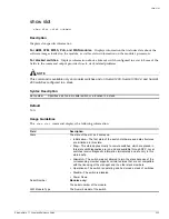
show slot
ExtremeWare 7.7 Command Reference Guide
355
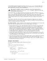
As the module progresses through its initialization, the
show slot <slot>
command displays the
general purpose processor (GPP) subsystem change state to OPERATIONAL, and then each of the
network processors will change state to OPERATIONAL.
When the GPP subsystem completes its initialization cycle and the subsystem state is
OPERATIONAL, use the
show diagnostics {<slot>}
command to check the results of the
module power-on self test (POST).
If the STATUS LED on the ARM, ATM, MPLS or PoS module turns amber and blinks, use the
show
slot <slot>
command to display the slot status information. The
show slot <slot>
command also
displays operational information related to the ARM, ATM, MPLS or PoS module. Information
displayed includes the BlackDiamond switch fabric card state (module state), Network Processor status,
General Purpose Processor status, hardware serial number and type, and image version and boot
settings.
For the ARM, ATM, MPLS, PoS, and WAN modules, the information displayed by this command
includes data about the software images loaded on the module and information about the operational
status and backplane connections of the module.
For stacked switches.
Displays information about a Summit switch configured in a stack. Some of the
fields in the command output provide clues to stack related problems. For example:
•
The slot state must be
operational
after the stack becomes active. If the slot is in any other state,
then the stack is not completely up. If the slot state indicates
mismatch
, then the member is not
allowed to join the stack because of operational vector problems. Operational vector mismatch
indicate that the corresponding slot supports certain features, which are not compatible with the
stack manager. For example, the member might be supporting an Advance-Edge license where the
manager supports only an Edge license. In this case, you must reconfigure the member
corresponding to the slot appropriately and must insert the member back into the stack.
•
The ports field indicates the link status of ports on the slot. If the stacking ports are not active, the
stack might be split at this point (based on the redundant link). You must ensure that the cables are
connected appropriately to the stacking ports.
•
The command also includes information regarding ExtremeWare versions, configuration and image
selected and booted for the particular slot. If the image versions mismatch the member is not
allowed to join the stack. You must ensure that all switches in the stack run compatible versions of
ExtremeWare while bringing up the stack
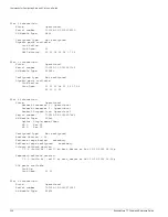
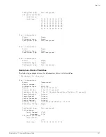
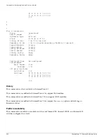
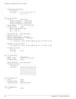
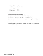
Example 1—Non-stacked
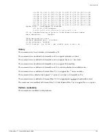
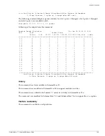
The following example displays module information for all slots:
show slot
Following is the output from this command:
Slot 1 information:
State: Operational
Serial number: 701028-06-0026F38445
HW Module Type: G8Ti
Configured Type: Not configured
UTP ports available:
Link Active:
Link Down: 01 02 03 04 05 06 07 08
Summary of Contents for ExtremeWare 7.7
Page 60: ...60 ExtremeWare 7 7 Command Reference Guide Contents ...
Page 72: ...72 ExtremeWare 7 7 Command Reference Guide Command Reference Overview ...
Page 404: ...404 ExtremeWare 7 7 Command Reference Guide VLAN Commands ...
Page 472: ...472 ExtremeWare 7 7 Command Reference Guide QoS Commands ...
Page 492: ...492 ExtremeWare 7 7 Command Reference Guide NAT Commands ...
Page 890: ...890 ExtremeWare 7 7 Command Reference Guide Security Commands ...
Page 1130: ...1130 ExtremeWare 7 7 Command Reference Guide Security Commands ...
Page 1164: ...1164 ExtremeWare 7 7 Command Reference Guide Configuration and Image Commands ...
Page 1436: ...1436 ExtremeWare 7 7 Command Reference Guide Wireless Commands ...
Page 1490: ...1490 ExtremeWare 7 7 Command Reference Guide EAPS Commands ...
Page 1576: ...1576 ExtremeWare 7 7 Command Reference Guide ESRP Commands ...
Page 1774: ...1774 ExtremeWare 7 7 Command Reference Guide IP Unicast Commands ...
Page 1914: ...1914 ExtremeWare 7 7 Command Reference Guide IGP Commands ...
Page 2000: ...2000 ExtremeWare 7 7 Command Reference Guide BGP Commands i Series Switches Only ...
Page 2140: ...2140 ExtremeWare 7 7 Command Reference Guide IPX Commands i Series Platforms Only ...
Page 2156: ...2156 ExtremeWare 7 7 Command Reference Guide ARM Commands BlackDiamond Switch Only ...
Page 2168: ...2168 ExtremeWare 7 7 Command Reference Guide Remote Connect Commands ...
Page 2346: ...2346 ExtremeWare 7 7 Command Reference Guide PoS Commands BlackDiamond Switch Only ...
Page 2446: ...2446 ExtremeWare 7 7 Command Reference Guide LLDP Commands ...
Page 2496: ...2496 ExtremeWare 7 7 Command Reference Guide H VPLS Commands BlackDiamond Switch Only ...
Page 2620: ...2620 ExtremeWare 7 7 Command Reference Guide Index of Commands ...

