background image

O p e r a t i o n     l    

4 - 6 9

4

Opera

tion

S e t u p   S c r e e n s  

( c o n t i n u e d )

N e t w o r k

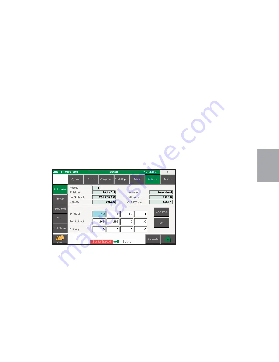
The system supports remote communications using a variety of protocols. Some of these
protocols use the built in TCP/IP port of the touch-panel, while others may require the addi-
tion of hardware. Multiple protocols can operate simultaneously over the touch-panels TCP
port. Some remote protocols will require an unlock code to enable. This page will configure
and setup the various protocols and required hardware.

When entering the unlock code, the station identifier will be presented. A Conair represen-
tative can use the station identifier code to generate the unlock code. The unlock code must
be correctly applied in order to enable the protocol.

For more information on the capabilities of Conair’s implementation of the protocol, refer
to the available protocol manual.

All remote protocol parameters will require a security level of {Service} to modify. Once a
protocol is enabled, or any protocol settings have been changed, the system will perform a
reboot sequence upon returning to the <Home> screen. When the reboot sequence is com-
pleted, the protocol will become available.

(Continued)

Summary of Contents for TrueBlend SB-4

Page 1: ...rueBlend Blender With SB 4 Control Corporate Office 724 584 5500 l Instant Access 24 7 Parts and Service 800 458 1960 l Parts and Service 814 437 6861 U S E R G U I D E UGB037 1118 www conairgroup com...

Page 2: ...er Guide and all manuals engineering prints and parts lists together for documentation of your equipment Date Manual Number UGB037 1118 Serial Number s Model Number s DISCLAIMER Conair shall not be li...

Page 3: ...anding the Parts of the TrueBlend SB 4 2 3 How it works TrueBlend 2 4 TrueBlend SB 4 System Components 2 5 Recipe Entry Modes 2 5 Resin and Product Names 2 5 Specifications TrueBlend 2 6 3 1 Installat...

Page 4: ...ecklist 5 2 Loading Equipment 5 3 Software Upgrades 5 3 Shutting Off in an Emergency 5 3 Restarting after Emergency Stop 5 3 Changing Material in a Blender Component 5 4 Cleaning the Mixer 5 6 Testing...

Page 5: ...Replacing Load Cells 6 9 A Appendix We re Here to Help A 1 How to Contact Customer Service A 1 Before You Call A 1 Equipment Guarantee A 2 Performance Warranty A 2 Warranty Limitations A 2 B Appendix...

Page 6: ...iv l Table of Contents...

Page 7: ...de Is Organized 1 2 Your Responsibilities as a User 1 2 ATTENTION Read This So No One Gets Hurt 1 3 Included Safety Features 1 4 How to Use the Lockout Device 1 5 Zero Mechanical State ZMS 1 6 S E C T...

Page 8: ...bers indicate tasks or steps to be performed by the user A diamond indicates the equipment s response to an action performed by the user An open box marks items in a checklist A circle marks items in...

Page 9: ...rom the incoming power supply must be connected to the chassis ground terminal inside the electrical enclosure Improper grounding can result in severe personal injury and erratic machine operation 120...

Page 10: ...ghly abrasive materials such as stones sand increased wear of unit components Poorly free flowing sticky materials airtight seal by the pneumatic cylinder is adversely affected Liquids and powders air...

Page 11: ...ockout device 1 Stop or turn off the equipment 2 Isolate the equipment from the electric power Turn the rotary disconnect switch to the OFF or O position 3 Secure the device with an assigned lock or t...

Page 12: ...adjustment or maintenance of the system 1 If there is a remote control device press the STOP key at that remote operator s control 2 Press the STOP key at the local TrueBlend SB 4 control panel 3 Dis...

Page 13: ...ations 2 2 How it works Understanding the Parts of the TrueBlend SB 4 2 3 How it works TrueBlend 2 4 TrueBlend SB 4 System Components 2 5 Recipe Entry Modes 2 5 Resin and Product Names 2 5 Specificati...

Page 14: ...aster automated start up helps create more quality product and generates less scrap The TrueBlend SB 4 Blender automatically adjusts for variations in material type density and geometry Typical Applic...

Page 15: ...ces the manual slide gate The pneumatic discharge slide gate is not installed if a manual slide gate is installed and the unit is mounted directly on the injection molding machine Hopper Loader Supply...

Page 16: ...er and is mixed and agitated by an electrically powered mixer into a homogeneous state The mixing chamber holds three batches After mixing the chamber is emptied by the discharge slide gate into the i...

Page 17: ...t recipe set up The recipe entry options available are configured from the Setup screen From the Home Screen press More Setup System Recipe From this screen you select whether your recipe is an Inject...

Page 18: ...ont view Side view SPECIFICATION NOTES Maximum throughput rates are based on 35 lb ft3 pel letized material using all standard valve sizes Use of reducer inserts will lower the rate shown Throughput r...

Page 19: ...ders Number of loaders 2 12 inch loaders Number of loaders 2 Top view Front view Side view SPECIFICATION NOTES Maximum throughput rates are based on 35 lb ft3 pel letized material using all standard v...

Page 20: ...NOTES Maximum throughput rates are based on 35 lb ft3 pelletized material using all standard valve sizes Use of reducer inserts will lower the rate shown Throughput rates are based on A 4 position ble...

Page 21: ...h loaders number of loaders 2 Top view Front view Side view Mounting bolt hole size 8 holes 9 16 inch 14 0 mm Predrilled 8 x 8 and 12 X 12 mounting pattern as standard SPECIFICATION NOTES Maximum thro...

Page 22: ...view Side view SPECIFICATION NOTES Maximum throughput rates are based on 35 lb ft3 pelletized material using all stan dard valve sizes Use of reducer inserts will lower the rate shown Throughput rate...

Page 23: ...Maximum throughput rates are based on 35 lb ft3 pelletized material using all standard valve sizes Use of reducer inserts will lower the rate shown Throughput rates are based on A 4 position blender...

Page 24: ...gredient ft3 liter 6 170 6 170 6 170 Bin capacity minor ingredient ft3 liter 6 170 4 113 4 113 Maximum number of materials 4 5 6 Number of major valves 4 5X5 3 5X5 2 5X5 Number of minor valves 0 2 2X5...

Page 25: ...S TB2500 4 TB2500 5 TB2500 6 Performance characteristics Batch size lbs g grams or kilograms 55 25000 55 25000 55 25000 Maximum throughput lbs hr kg hr 9000 4082 8000 3629 7000 3175 Bin capacity main...

Page 26: ...de view B C 6 5 4 5 A NOTE Side and front view drawings are shown for model TB3500 6 The bin positions change for a TB3500 4 and TB3500 5 models see the top view I G MODELS TB3500 4 TB3500 5 TB3500 6...

Page 27: ...minor ingredient ft3 liter 0 3 8 1 6 45 3 2 7 76 4 4 4 124 6 Maximum number of materials 4 4 4 4 Number of vertical discharge valves 4 4 4 4 Number of major bin valves 2 60 mm 2 60 mm 2 100 60 mm 2 10...

Page 28: ...Capacitance Sensor Connections Satisfactory State When there is no alarm condition this outlet will supply a continuous flow of 110V 220V single phase power Only during an alarm will the power supply...

Page 29: ...5 Layout of the Material Hoppers 3 6 Mounting the Loaders 3 6 Connecting Compressed Air 3 7 Installing the Weigh Bin 3 7 Connecting the Main Power 3 7 Preparing for Electrical Installation 3 8 Testing...

Page 30: ...on the options selected HMI operator panel Control cable to connect the control to the electrical cabinet Weigh bin Slide gate option User manual and wiring diagrams not shown 1 Carefully unwrap the...

Page 31: ...electrical wiring should comply with your region s electrical codes Clearance for safe operation and maintenance A compressed air supply It is necessary to supply compressed air to the blender Your pl...

Page 32: ...te bolt size You are responsible for the structural integrity of your installation Make sure to use the largest bolt that will fit properly into the through hole Use the hardware supplied to bolt the...

Page 33: ...tor cable between the HMI control and the electrical cabinet The cable connects from the back of the box to the fitting underneath the bottom of the electrical cabinet Tighten the screws on the plug N...

Page 34: ...your loader for specific instructions 4 Refer to the wiring diagrams that were shipped with your blender and loaders Layout of the Material Hoppers 4 position 6 position Position 1 Position 2 Position...

Page 35: ...tected by properly sized protectors fuses or breaker IMPORTANT Always refer to the wiring diagrams that came with your blender to locate specific electrical components Illustrations in the User Guide...

Page 36: ...data only needs to be entered once as it is stored in battery backed memory In addition some of the configuration vari ables have default values which in most cases do not need to be changed A config...

Page 37: ...OK button to obtain the Zero Weight Calibration Factor Please stand by while the system obtains the Zero Weight Calibration Factor 7 Enter the Test Weight Value then press OK 8 Place the test weight i...

Page 38: ...3 10 l Installation...

Page 39: ...on The TrueBlend SB 4 Operator Control Panel 4 2 Loading Material into the TrueBlend SB 4 Hoppers 4 3 Starting the Blending Process 4 3 Stopping the Blending Process 4 3 Security Settings 4 3 Touch Pa...

Page 40: ...4 2 l Operation The TrueBlend SB 4 Operator Control Panel Home Screen This is the home screen for the blender Home Screen This is the home screen with Job Mode turned on...

Page 41: ...her the current batch should be allowed to finish before stopping or should the blender stopped immediately without complet ing the batch 3 Enter the appropriate stop mode or press Back to not stop th...

Page 42: ...ive as well User Interface The user interface presented on the touch screen is a collection of pages or screens which can be used to monitor and control the system The TrueBlend SB 4 system is designe...

Page 43: ...ea contains a variety of information displaying the operational status of the sys tem On the bottom left of the screen is the Alarm button which navigates to the Active Alarms screen The alarm button...

Page 44: ...Reports Setup and Help areas of the system They are used to select a type of Report an area of the Setup system or a specific Help document Basic Navigation Buttons There are several navigation butto...

Page 45: ...Page Up Move up a full page of text in the text box Page Down Move down a full page of text in the text box Line Up Move up a line of text within the text box Line Down Move down a line of text within...

Page 46: ...played There is firmware protection built into the system Powering the system on for the first time with new software requires a software licensing code to be entered in order to contin ue the boot pr...

Page 47: ...is replaced with the name of the resin in the component hopper The hoppers are numbered clockwise similar to the numbering scheme of the com ponent hoppers on the physical blender If the hopper is exp...

Page 48: ...ipe button Whenever a new recipe has been entered the text on the Automatic button will change to Commit and the indicator light will change to yellow This is an indication that a new recipe has been...

Page 49: ...Command Bar Automatic Places the Blender into automatic operation This action requires a valid recipe be entered from the Recipe screen The button will show a green indicator if in automatic If the r...

Page 50: ...y navigating to Setup Panel Panel This will change the default display language It is also possible to change the display lan guage without going into Setup This will temporarily change the displayed...

Page 51: ...be accessed 2 Orange Setup Passcode 2222 This level of security allows for various blender setup parameters to be adjusted Upon returning to the Home screen the new setup parameters will be saved 3 R...

Page 52: ...tion of the available Chapters Along the left side of the screen are selection buttons that select a Section of documents that pertain to the chosen chapter Across the bottom of the screen are selecti...

Page 53: ...ton will navigate the operator to the active alarms screen The logged alarm list can then be viewed by pressing the Alarm Log button located on the Active Alarm screen Shutdown Alarm RedThis alarm sev...

Page 54: ...s may be acknowledged by pressing the Acknowledge button Press the Alarm Log button to view the Logged Alarms screen Press the Reports button to navigate to the Report screen to output the alarm list...

Page 55: ...the list will appear color coded based on the severity of the alarm at the time it was triggered If he alarm condition is white the alarm condition is no longer occurring A Clear All button is presen...

Page 56: ...t least Operator level of security Clear All Clear the logged alarm llist of all entries Report Send the logged alarm list to an outputdevice such as a printer or USB thumb drive Recipe Errors Recipe...

Page 57: ...he alarm and the device where the alarm occurred Content Sensitive Help Using the navigation buttons in the Alarms section it is possible to highlight select any alarm in the list Once selected the He...

Page 58: ...problem Each report includes a header which identifies the production line report time report name and the name of the system All reports can be formatted as either a comma separated file csv or as a...

Page 59: ...e Alarm State Acknowledge Status Device Name Alarm Message Active Alarm Report This report will output the entire list of current active alarms For active alarms only the current state is listed For n...

Page 60: ...er in the system To generate an on demand report 1 In the On Demand section select the type of report to be generated from the pull down menu 2 Select the format of the report output from the pull dow...

Page 61: ...Resin Report Loading Report Select the type of report you wish to gener ate Report Style Formatted Report Comma Separated Data File Select the output format or style you wish to generate Select Desti...

Page 62: ...ation selected If the space exceeds 4 Gigabytes the value shown will be 4Gb 5 Press the Run Report button to generate the report When complete the report will be shown in a Report View popup window 6...

Page 63: ...also be set Recipe Data The current recipe is saved whenever the Auto or Stop button is pressed Thicknes With TrueBlendExt if thickness mode is enabled the calculated product thickness is output accor...

Page 64: ...communications with the PC can be made When the connection between the blender and TBReports on the PC is operating correctly the Status text will update with the text Connected and the back ground w...

Page 65: ...t Name 4 char String Identification name of the blender in TBReports Shift Inventory Report Yes No Enable the shift inventory output Shift Report Start Time HH MM HH 7 MM 30 7 30 am The first time of...

Page 66: ...t a file from the file list The selected drive path and file will be shown in the Path field 3 Press the View File button to display the selected report 4 Press the Back button to close the report vie...

Page 67: ...mmed together for a system total Three types of material consumption totals are accumulated in the system The first is the running total labeled Total Inventory The second is called Shift Totals which...

Page 68: ...e selected recipe will be accumulated as a Recipe Total The Recipe Totals screen shows the recipe totals for all recipes in the Recipe Book The screen shows a table of 10 recipe totals Each entry in t...

Page 69: ...y entering the desired resin num ber The selected resin is shown with a light blue background and arrow icon pointing to the entry The accumulated total for the selected resin item can be cleared by p...

Page 70: ...recipe errors must first be corrected If there are no errors with the recipe the system will go into Automatic and process ing will begin The New Recipe is copied to the Set Current Recipe and the sy...

Page 71: ...ercent Add N For Injection Recipe Entry only the additive natural material type is metered as a percentage of Natural materials Add B For Injection Recipe Entry only the additive batch material type i...

Page 72: ...ment the changes to the recipe Recipe Book Navigate to the Recipe Book screen This is where stored recipes can be edited and selected for use Material Calibration Launch the material calibration popup...

Page 73: ...Note When using Resin Codes the resins solid density is defined and will be used if needed Feed Order If Feed Order in Recipe is enabled this data entry field is present The operator can enter the de...

Page 74: ...o insure both a proper blend and target job weight If the blender is stopped and started before the Target Weight is reached a popup window will ask the operator if the Actual Job Weight should be cle...

Page 75: ...r correctness The val idation process only takes place when Commit is pressed Therefore caution should be taken when entering a recipe into the book In order to insure a valid recipe entry it is possi...

Page 76: ...correct security level which is configurable in Setup they can press the Upload button to copy the produc tion recipe into the book A popup will be presented where the operator selects the recipe numb...

Page 77: ...ter the name of the recipe 15 characters maximum Save the changes by press ing the Save button NOTE Recipe validation does not take place until the Commit button is pressed Entering an invalid recipe...

Page 78: ...lected resin box There are a total of 255 resin locations available After verifying the resin and its density press the select button to use the selected resin The density value is critical for extrus...

Page 79: ...mage is actually the face of a button and pressing the image will disable or enable the specific loader Below the bitmap is a button with the loader name shown Pressing the Loader Name button will nav...

Page 80: ...th material Discharging Dumping The loader body fill sequence has completed and it is currently dumping material Disabled The blower is disabled The pump is not being monitored or controlled and any f...

Page 81: ...page These values can also be found in setup Load Time sec 10 2 180 Operator The amount of time the loader body will actively load material Alarm Time sec 120 0 3600 Operator This is the amount of ti...

Page 82: ...n below the pump will navigate to a page where further information regarding the pump can be found Diagnostics Simple diagnostic information is provided for the pump which indicates the number of pump...

Page 83: ...p a parameter needs to be changed touch the desired input field If the user does not have proper security a security popup screen will appear where the user can input a new security passcode If the sy...

Page 84: ...Network This device provides for configuration and setup of remote communications and networking support Maintenance This area provides various support functions for file IO licensing and Manual Cont...

Page 85: ...ains parameters that configure and define several programmable relay functions Alarm This section contains parameters that configure the severity and action of all alarms in the system with respect to...

Page 86: ...f material component hoppers available on the blender Product Model TB45 4 Various Models Service Stopped Select the model of blender The product model will set various parameters for the number of fe...

Page 87: ...rrelation of component entry values and whether the ratio must add to 100 Use Order Names No Yes No Service Stopped The system can show an order name on the mon itor screens or for reporting purposes...

Page 88: ...meters are Parameter Default Range Security Description Selected Relay None Hand Control Input System Running Output Job Start Input Select a relay to configure Enable Relay No Yes No Yes No Service S...

Page 89: ...ng Yes on the popup will reset the alarm database Pressing No will exit the popup and NOT clear the alarm database This action requires a security mode of Service Stopped Alarm Database Configuration...

Page 90: ...tomatic various Info General Shutdown Service For each operating state of the system the severity of the selected device and alarm combination is shown with a pull down menu Using the pull down menu i...

Page 91: ...ange Security Description Name Trueblend various Service The name of the system as it will appear throughout the touch screen pages and on reports Production Line Name Line 1 various Service This defi...

Page 92: ...up The base number system shown by the touch panel If extru sion control is enabled additional settings are provided for key unit types Weight Length lbs 100ft kg m lbs 1000ft lbs ft kg m g m Setup Th...

Page 93: ...security 3 of which each have a passcode The passcodes allow the user to raise the level of security to unlock various features Some user actions may have programmable security level locking This page...

Page 94: ...security level required to modify recipes and resins in the Recipe Book Level to Calibrate Operator Guest Operator Setup Service Service The security level required to calibrate the weighed hoppers L...

Page 95: ...hift is also output to SQL The basic time and date settings are Shift This button will present a popup window where the work shift times and names can be configured Shift Configuration Setup The syste...

Page 96: ...the following days report Care will have to be taken when selecting the report time filter Parameter Default Range Security Description Name Shift 1 Shift 2 Shift 3 various 11 char Setup The name of...

Page 97: ...ns Control This page is for setting up control settings for the gate feeder hopper Alarm This screen sets parameters which control when a component alarm might occur Control This page is for setting u...

Page 98: ...Table Resolution ms 10 5 999 Setup Stop The time difference in milliseconds between the first 10 entries in the feed table for small resolution feed rates Settling Time ms 800 0 9999 Service The amou...

Page 99: ...Weight allowed before an Out of Material alarm is generated Minimum Feed Weight g 0 1 0 1 0 999 Service Minimum amount of weight fed before an out of mate rial condition occurs Also used to determine...

Page 100: ...nto the batch one at a time according to the parameters defined by the recipe When the batch is complete the hopper will dump the material into the mixing chamber below if the mixer is requesting mate...

Page 101: ...ty Weight Tolerance lb 0 3 0 5 Setup The weight tolerance that will indicate an empty weigh hopper Leak Detection Percentage 20 0 100 Setup Maximum percentage the batch weight is allowed to rise when...

Page 102: ...le High Temperature Mode No Yes No Setup Set to Yes to force the batch hopper to dump itself out then wait to make a new batch once mixer dumps out Batch Rate Update Count 2 1 20 Setup Number of times...

Page 103: ...n test weight inside on the hopper Now allow the system to get a reference of a known weight Remove the test weight From these reference points it is now possible to accurately determine the weight of...

Page 104: ...the OK button to obtain the Zero Weight Calibration Factor Please stand by while the system obtains the Zero Weight Calibration Factor 3 Enter the Test Weight Value and then press OK The test weight s...

Page 105: ...ens are used to set parameters that are relevant to the mixing device Parameters include Control Parameters Mixer Device Sections Control This page is for setting up control settings for the mixer Ala...

Page 106: ...is stirred The mix motor will then run for several seconds Idle Mix Time sec 3 0 9999 Setup The amount of time the mixer motor runs to blend the material after the batch hopper empties The amount of t...

Page 107: ...ware When entering the unlock code the station identifier will be presented A Conair represen tative can use the station identifier code to generate the unlock code The unlock code must be correctly a...

Page 108: ...es are made to these parameters a reboot of the system will be performed upon returning to the Home screen TCP IP Settings For the following parameters the current set values are shown along with fiel...

Page 109: ...e a protocol is enabled or any protocol settings have been changed the system will perform a reboot sequence upon returning to the Home screen When the reboot sequence is com pleted the protocol will...

Page 110: ...Address of the remote system be defined This protocol will also require a double reboot of the touch screen The first reboot will enable the protocol and the second reboot will acknowledge the remote...

Page 111: ...on In order to set up a serial protocol the port where the protocol will reside must first be cho sen Once a serial port has been chosen the remaining parameters will populate according ly The basic s...

Page 112: ...e basic email settings are Parameter Default Range Security Description Enable Email No Yes No Service Stop The email feature must be enabled to operate This will require a security unlock code SMTP A...

Page 113: ...nair database and the proper tables and relationships have been established within the server Conair can provide documentation that shows the contents of the tables and relationship mappings Parameter...

Page 114: ...abase Name ConairIPEG 11 character string Service Stop The name of the database defined in the SQL Server Server Port 1433 Plain Login SSL TSL Service Stop The port used by the SQL Server Server IP Ad...

Page 115: ...lock code in order to enable Inventory Data HH 1 0 23 Service 24 hour clock hour interval value for when the inventory data is saved to database Inventory Data MM 0 0 59 Service 24 hour clock minute i...

Page 116: ...identifier and the unlock codes for any locked features System This section provides for basic system functions Factory Defaults Touch screen alibration and Safe Screen Cleaning Defaults Security Ser...

Page 117: ...Network screen The touch panel must be connected to the PC with the FTP client via standard Ethernet practices Internal Hard Drive Compact Flash F There is an internal flash drive available for stora...

Page 118: ...etup This button will delete the selected file from the selected path Clear All Setup This button will delete all of the selected files from the selected path Reload This button will refresh the direc...

Page 119: ...the event of a firmware update the resin list can be saved and reloaded after the firmware update is completed With identical systems it is also possible to copy the resin list from one system to anot...

Page 120: ...curity level required to operate the blender manually can be uniquely configured on the system security setup screen Disabled This is toggle button for controlling a digital output that is NOT control...

Page 121: ...red If the code is invalid or unavailable the popup window will close and the feature will be disabled The Station Identifier must be provided to a Conair representative in order to generate the unloc...

Page 122: ...x 14 character string Setup Stop The name of the blower pump Blower Address NodeID 1 255 Setup Stop The Node ID of the touch panel where the pump resides The Node ID is configured via Setup IP Address...

Page 123: ...loaders there are additional previous and next buttons to navigate through all loader bodies The set parameters shown will be for the selected loader Loader Device Sections System This page is for set...

Page 124: ...e NodeID for the blending system where the pump resides that services the loader body If the pump is on the remote blender the NodeID will be that of the remote blender If the pump is local the NodeID...

Page 125: ...Time sec 10 2 180 Operator The amount of time the receiver body will load with material Dump Time sec 5 2 180 Operator The amount of time the receiver body will dump the material First Fill sec 5 2 6...

Page 126: ...ore Setup System Control For Loading Enabled select Control and enter the license code 7 The self loading feature should now be enabled Ethernet addresses set and the nodeID for both systems set This...

Page 127: ...d service personnel should use this area The user must have Service level security to enter diagnostics To navigate to the Diagnostic screens first navigate to the Home page At the Home screen press t...

Page 128: ...are shown on the electrical enclosure drawing supplied with the system The X20 slice provides the IO required by the system The configuration of the system determines the required IO and also the req...

Page 129: ...is BAD There is most likely a missing slice a failed slice or the wrong type of slice is installed in the slot Green and Red LED The slice is OK the primary power bus to the slice is indicat ing a pr...

Page 130: ...is in Test Mode Manual mode touching the slice graphic or the slice Type button a detail view of the slice is presented The status of any Inputs Outputs will also be shown In this mode the descriptiv...

Page 131: ...weight of material detected in the batch hopper and indicates variation or vibration that is occurring on the batch hopper Raw AD Output This value is a digital representation of the weight detected b...

Page 132: ...uttons to navigate through all component hoppers The diagnostics shown will be for the selected component Feed Table This section will present the feed table for the selected component hopper Feed Tab...

Page 133: ...f material the last feed sequence was requesting Actual The actual amount of material the last feed sequence received Feed Count The number of times the component gate was opened during the last feed...

Page 134: ...4 96 l Operation...

Page 135: ...Mixer 5 6 Testing the Safety Interlock Function 5 7 Draining the Water Separator 5 7 Inspecting Hoses 5 7 Removing and Installing the Mixing Chamber 5 8 Calibrating Adjusting the Sensor 5 8 Replacing...

Page 136: ...schedule and tasks Whenever you change materials Check EMERGENCY STOP function Test the safety interlock switch Clean the extruder weigh hopper s Monthly or as often as needed Inspect hoses for damage...

Page 137: ...supply is interrupted If the cone valve was open it is closed All other machine movement is stopped immediately The batch is not finished The main switch can also be locked manually with a lock Restar...

Page 138: ...al vibration from the process There is a separate retainer for each detachable hopper To remove any of these detachable hoppers for cleaning or material changeover 1 Remove the automatic loading recei...

Page 139: ...tically into the respec tive valve opening and raise the plunger cone to allow materials to flow from the material compartments Material will flow out of the hopper compartment through the valve openi...

Page 140: ...The safety switch will prevent operation of the mixer with the door open Tip If using the optional drain chute with safety interlock open the front access door remove the weigh bin and position the ch...

Page 141: ...alve Testing the Safety Interlock Function Test the safety interlock function by opening the mixer chamber door The alarm should sound and the blender should stop Check the component hopper safety int...

Page 142: ...eing flush and still allow access to push button and indicator light should be facing away from mixing motor towards the outside of the unit 2 Make sure the supplied nut is installed in the back of th...

Page 143: ...de is invisible but the material will still be sensed during operation For most applications setting the sensor with no material in the vessel is sufficient A large amount of fines or regrind or a low...

Page 144: ...2 5 Remove the complete unit 6 Reassemble in reverse order Note the stroke when installing otherwise the desired throughput may not be reached NOTE When disassembling the cylinder valve assembly meas...

Page 145: ...e load cell to the appropriate location in the control box 4 Complete an empty and full calibration see the Operation section entitled Menus Hopper Setup Calibration and operate as normal WARNING Elec...

Page 146: ...that the weigh bin mount and the weigh pan sit centered in the blender chassis unobstructed and not touching either side 5 Once the load cell is adjusted correctly reinstall the weigh bin mount to the...

Page 147: ...allation and Adjustment Models TB250 TB500 TB900 The weigh bin needs to set freely in the bottom of the slots and the hoses are to be connect ed in the quick disconnects NOTE Weigh bin mount adjustmen...

Page 148: ...he load cell to the load cell mounting bracket 11 and remove the old cell Tip There is no need to remove the stop screw 9 and lock nut 10 during removal of the load cell It should remain in place so n...

Page 149: ...be removed and installed easily The weigh bin should be installed so it is centered in the chassis and does not contact the weigh bin when the cylinder is at rest Once satisfied with placement tighten...

Page 150: ...is set tighten the two nuts Alternatively this can be set by either hanging a weight of 10 kg on each individual load cell hanger brack et or reinstalling the weigh bin and loading it with a total we...

Page 151: ...Caution 6 2 How to Identify the Cause of a Problem 6 3 Signaling Alarm Message 6 3 Handling Alarm Messages 6 3 Alarms 6 4 Basic Alarms 6 5 Replacing Fuses 6 8 Replacing Load Cells 6 9 S E C T I O N 6...

Page 152: ...als for the equipment located upstream and down stream from the TrueBlend SB 4 system Solving problems related to material coveyed to the TrueBlend SB 4 or due to poor extrusion or injection quality m...

Page 153: ...in the system the Alarms key appears in the lower left corner of the display The color of this key will reflect the severity level of the most severe active alarm Press the Alarms key to navigate to a...

Page 154: ...e component bin that is causing the alarm It is important to look at the alarm text and check to see if there is a problem with the component bin number listed For example the alarm code Component 2 O...

Page 155: ...st mixer proximity switch so the material from the batch weigh hopper is allowed to drain fully into the mixer Eliminate all mechanical interference with batch weigh hopper In Setup Component Advanced...

Page 156: ...dware and Loading Option Software is enabled Alarm occurs if there are TWO blenders being loaded with ONE vacuum Pump AND the Ethernet communication link between the two blender touch screens has fail...

Page 157: ...If the new calculat ed batch size is greater than the setup parameter Setup Batch Hopper Over size Batch then this alarm occurs Solution Occurs if 24vdc is removed or X2X network communication is los...

Page 158: ...cuit Located inside the TrueBlend SB 4 electrical control panel are fuses for the AC line FU1 and the power supply output side FU2 and FU3 To replace a blown fuse 1 Disconnect and lockout the main pow...

Page 159: ...ue of 10 Nm Do NOT use excessive force Forces that are exerted on the load cell from outside when attaching and removing the TrueBlend SB 4 extruder hopper load cell may damage the very sensitive load...

Page 160: ...6 10 l Troubleshooting...

Page 161: ...serial tag and parts list numbers for your particular equipment Service personnel will need this information to assist you Make sure power is supplied to the equipment Make sure that all connectors a...

Page 162: ...tions Inspect the equipment and perform alterations or adjustments to satisfy performance claims Charges for such inspections and corrections will be waived unless failure to meet warranty is due to m...

Page 163: ...m the fol lowing table Example Blender XYZ Component 1 3 X 6 valve 4000 g s Component 2 3 X 6 valve 4000 g s Component 3 2 X 3 valve 850 g s Component 4 2 X 3 valve 850 g s Component 5 2 i d feeder 40...

Page 164: ...and tighten Use thread tape where needed If the compressed air quality is poor and has contami nants in it the fitting should be installed on the outlet side of the regulator The illus tration shows r...

Page 165: ...Appendix l C 2 Hole Locations for Blow Off Kit...

Page 166: ...nd loosen lock nuts that adjust the length of the assembly as required from step 4 Re install assembly and re check mixing chamber closing Once the length is correct place a small amount of Loctite on...

Page 167: ...e blender 3 Organize the piping from the dryer to the blender 4 Loosely make all connections between the blender and the dryer making sure to install the slide gates where necessary 5 Tighten all conn...

Page 168: ...D 3 l Appendix...

Reviews: