
APPENDIX
App. - 33
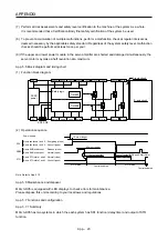
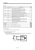
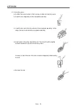
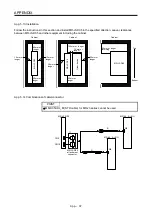
(3) Connector insertion
Insert the connector all the way straight until you hear or feel clicking. When removing the connector,
depress the lock part completely before pulling out. If the connector is pulled out without depressing the
lock part completely, the housing, contact and/or wires may be damaged.
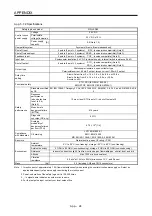
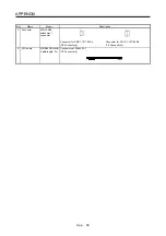
(4) Compatible wire
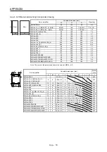
Compatible wire size is listed below.
Wire size
mm
2
AWG
0.22 24
0.34 22
0.50 20
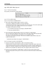
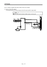
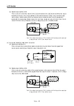
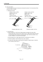
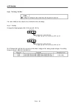
(5) Others
(a) Fix a cable tie keeping a distance of "A" × 1.5 or longer from the end of the connector.
A × 1.5 or more
A
(b) Be sure that wires are not pulled excessively when the connector is inserted.
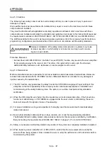
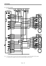
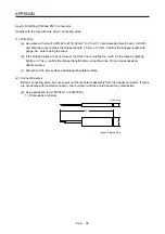
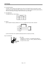
App. 5.8.4 Wiring FG
Bottom face
Lead wire
Wire range
Single
wire:
φ
0.4 mm to 1.2 mm (AWG 26 to AWG 16)
Stranded wire: 0.2 mm
2
to 1.25 mm
2
(AWG 24 to AWG 16),
wire
φ
0.18 mm or more
Содержание MR-J4-100A(-RJ)
Страница 19: ...10 MEMO ...
Страница 75: ...1 FUNCTIONS AND CONFIGURATION 1 56 MEMO ...
Страница 83: ...2 INSTALLATION 2 8 MEMO ...
Страница 159: ...3 SIGNALS AND WIRING 3 76 MEMO ...
Страница 203: ...4 STARTUP 4 44 MEMO ...
Страница 351: ...7 SPECIAL ADJUSTMENT FUNCTIONS 7 40 MEMO ...
Страница 365: ...8 TROUBLESHOOTING 8 14 MEMO ...
Страница 387: ...9 DIMENSIONS 9 22 MEMO ...
Страница 403: ...10 CHARACTERISTICS 10 16 MEMO ...
Страница 553: ...12 ABSOLUTE POSITION DETECTION SYSTEM 12 30 MEMO ...
Страница 567: ...13 USING STO FUNCTION 13 14 MEMO ...
Страница 607: ...14 COMMUNICATION FUNCTION MITSUBISHI ELECTRIC GENERAL PURPOSE AC SERVO PROTOCOL 14 40 MEMO ...
Страница 639: ...15 USING A LINEAR SERVO MOTOR 15 32 MEMO ...
Страница 767: ...18 MR J4 03A6 RJ SERVO AMPLIFIER 18 84 MEMO ...
Страница 856: ...APPENDIX App 41 ...
Страница 905: ...MEMO ...


