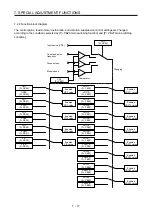
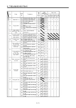
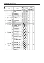

7. SPECIAL ADJUSTMENT FUNCTIONS
7 - 31
7.4 Compliance with SEMI-F47 standard
POINT
The control circuit power supply of the MR-J4-_A_(-RJ) 100 W or more servo
amplifier can comply with SEMI-F47 standard. However, a back-up capacitor
may be necessary for instantaneous power failure in the main circuit power
supply depending on the power supply impedance and operating situation.
Use a 3-phase for the input power supply of the servo amplifier. Using a 1-phase
100 V AC/200 V AC for the input power supply will not comply with SEMI-F47
standard.
The external dynamic brake cannot be used for compliance with SEMI-F47
standard. Do not assign DB (Dynamic brake interlock) in [Pr. PD23] to [Pr.
PD26], [Pr. PD28], and [Pr. PD47]. Failure to do so will cause the servo amplifier
to become servo-off when an instantaneous power failure occurs.
Be sure to perform actual machine tests and detail checks for power supply
instantaneous power failure of SEMI-F47 standard with your equipment.
The MR-J4-03A6(-RJ) servo amplifier is not compatible with SEMI-F47
standard.
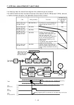
The following explains the compliance with "SEMI-F47 semiconductor process equipment voltage sag
immunity test" of MR-J4 series.
This function enables to avoid triggering [AL. 10 Undervoltage] using the electrical energy charged in the
capacitor in case that an instantaneous power failure occurs during operation.
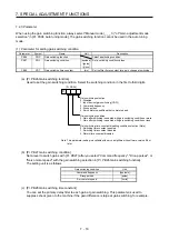
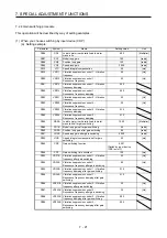
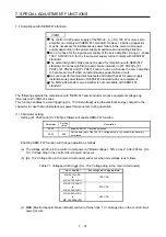
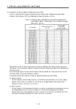
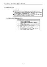
(1) Parameter setting
Setting [Pr. PA20] and [Pr. PF25] as follows will enable SEMI-F47 function.
Parameter
Setting
value
Description
PA20
_ 1 _ _ Enable SEMI-F47 function selection.
PF25 200
Set the time [ms] of the [AL. 10.1 Voltage drop in the control circuit power]
occurrence.
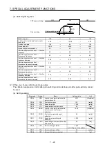
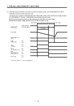
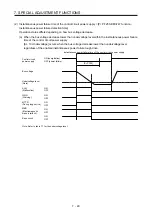
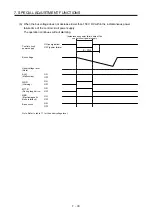
Enabling SEMI-F47 function will change operation as follows.
(a) The voltage will drop in the control circuit power at "Rated voltage × 50% or less". After 200 ms, [AL.
10.1 Voltage drop in the control circuit power] will occur.
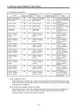
(b) [AL. 10.2 Voltage drop in the main circuit power] will occur when bus voltage is as follows.
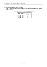
Table 7.1 Voltages which trigger [AL. 10.2 Voltage drop in the main circuit power]
Servo amplifier
Bus voltage which triggers alarm
MR-J4-10A(-RJ)
to
MR-J4-700A(-RJ)
158 V DC
MR-J4-11KA(-RJ)
to
MR-J4-22KA(-RJ)
200 V DC
MR-J4-60A4(-RJ)
to
MR-J4-22KA4(-RJ)
380 V DC
(c) MBR (Electromagnetic brake interlock) will turn off when [AL. 10.1 Voltage drop in the control circuit
power] occurs.
Содержание MR-J4-100A(-RJ)
Страница 19: ...10 MEMO ...
Страница 75: ...1 FUNCTIONS AND CONFIGURATION 1 56 MEMO ...
Страница 83: ...2 INSTALLATION 2 8 MEMO ...
Страница 159: ...3 SIGNALS AND WIRING 3 76 MEMO ...
Страница 203: ...4 STARTUP 4 44 MEMO ...
Страница 351: ...7 SPECIAL ADJUSTMENT FUNCTIONS 7 40 MEMO ...
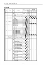
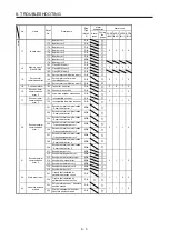
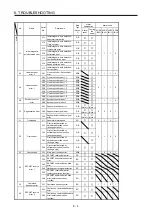
Страница 365: ...8 TROUBLESHOOTING 8 14 MEMO ...
Страница 387: ...9 DIMENSIONS 9 22 MEMO ...
Страница 403: ...10 CHARACTERISTICS 10 16 MEMO ...
Страница 553: ...12 ABSOLUTE POSITION DETECTION SYSTEM 12 30 MEMO ...
Страница 567: ...13 USING STO FUNCTION 13 14 MEMO ...
Страница 607: ...14 COMMUNICATION FUNCTION MITSUBISHI ELECTRIC GENERAL PURPOSE AC SERVO PROTOCOL 14 40 MEMO ...
Страница 639: ...15 USING A LINEAR SERVO MOTOR 15 32 MEMO ...
Страница 767: ...18 MR J4 03A6 RJ SERVO AMPLIFIER 18 84 MEMO ...
Страница 856: ...APPENDIX App 41 ...
Страница 905: ...MEMO ...


