
3. SIGNALS AND WIRING
3 - 33
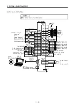
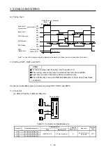
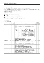
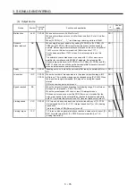
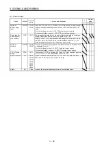
Device Symbol
Connector
pin No.
Function and application
I/O
division
Control
mode
P S T
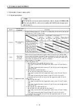
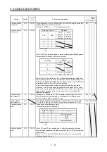
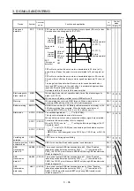
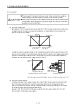
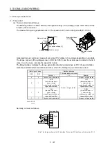
Proportion control
PC
CN1-17 Turn PC on to switch the speed amplifier from the proportional integral type
to the proportional type.
If the servo motor at a stop is rotated even for a pulse due to any external
factor, it generates torque to compensate for a position shift. When the
servo motor shaft is to be locked mechanically after positioning completion
(stop), switching on the PC (Proportion control) upon positioning
completion will suppress the unnecessary torque generated to compensate
for a position shift.
When the shaft is to be locked for a long time, switch on the PC
(Proportion control) and TL (External torque limit selection) at the same
time to make the torque less than the rated by TLA (Analog torque limit).
Do not use PC (Proportional control) in the torque control. Doing so may
cause the operation to be performed at a speed exceeding the speed limit
value.
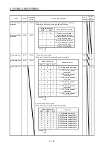
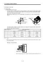
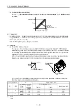
DI-1
Clear
CR
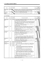
CN1-41 Turn CR on to clear the position control counter droop pulses on its leading
edge. The pulse width should be 10 ms or longer.
The delay amount set in [Pr. PB03 Position command
acceleration/deceleration time constant] is also cleared. When " _ _ _ 1 " is
set to [Pr. PD32], the pulses are always cleared while CR is on.
DI-1
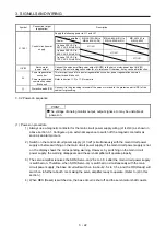
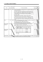
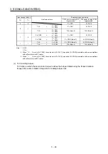
Electronic gear
selection 1
CM1
The combination of CM1 and CM2 enables you to select four different
electronic gear numerators set in the parameters.
CM1 and CM2 cannot be used in the absolute position detection system.
DI-1
(Note) Input device
Electronic gear numerator
CM2
CM1
0
0
Pr.
PA06
Electronic gear
selection 2
CM2
0 1
Pr.
PC32
DI-1
1
0
Pr.
PC33
1
1
Pr.
PC34
Note. 0: Off
1: On
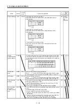
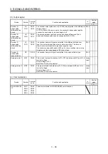
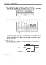
Gain switching
CDP
Turn on CDP to use the values of [Pr. PB29] to [Pr. PB36] and [Pr. PB56]
to [Pr. PB60] as the load to motor inertia ratio and gain values.
DI-1
Содержание MR-J4-100A(-RJ)
Страница 19: ...10 MEMO ...
Страница 75: ...1 FUNCTIONS AND CONFIGURATION 1 56 MEMO ...
Страница 83: ...2 INSTALLATION 2 8 MEMO ...
Страница 159: ...3 SIGNALS AND WIRING 3 76 MEMO ...
Страница 203: ...4 STARTUP 4 44 MEMO ...
Страница 351: ...7 SPECIAL ADJUSTMENT FUNCTIONS 7 40 MEMO ...
Страница 365: ...8 TROUBLESHOOTING 8 14 MEMO ...
Страница 387: ...9 DIMENSIONS 9 22 MEMO ...
Страница 403: ...10 CHARACTERISTICS 10 16 MEMO ...
Страница 553: ...12 ABSOLUTE POSITION DETECTION SYSTEM 12 30 MEMO ...
Страница 567: ...13 USING STO FUNCTION 13 14 MEMO ...
Страница 607: ...14 COMMUNICATION FUNCTION MITSUBISHI ELECTRIC GENERAL PURPOSE AC SERVO PROTOCOL 14 40 MEMO ...
Страница 639: ...15 USING A LINEAR SERVO MOTOR 15 32 MEMO ...
Страница 767: ...18 MR J4 03A6 RJ SERVO AMPLIFIER 18 84 MEMO ...
Страница 856: ...APPENDIX App 41 ...
Страница 905: ...MEMO ...


