

5. PARAMETERS
5 - 48
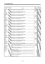
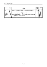
No./symbol/
name
Setting
digit
Function
Initial
value
[unit]
Control
mode
P S T
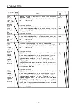
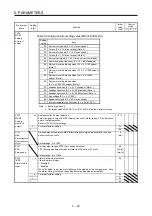
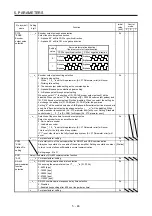
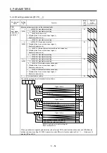
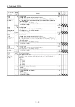
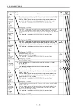
PC26
*COP5
Function
selection C-5
_ _ _ x [AL. 99 Stroke limit warning] selection
Enable or disable [AL. 99 Stroke limit warning].
0: Enabled
1: Disabled
0h
_ _ x _ For manufacturer setting
0h
_ x _ _
0h
x _ _ _
0h
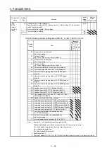
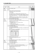
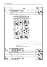
PC27
*COP6
Function
selection C-6
_ _ _ x [AL. 10 Undervoltage] detection method selection
Set this parameter when [AL. 10 undervoltage] occurs due to power supply voltage
distortion while using FR-RC-(H) or FR-CV-(H).
0: When [AL. 10] does not occur
1: When [AL. 10] occurs
This digit is not available with MR-J4-03A6(-RJ) servo amplifiers.
When using the MR-J4-_A-RJ servo amplifier with the DC power supply input, set "1".
DC power supply is available with MR-J4-_A-RJ servo amplifiers with software
version C2 or later.
0h
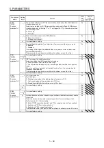
_ _ x _ Main circuit power supply selection
Select a voltage to be connected to the main circuit power supply with an MR-J4-
03A6(-RJ) servo amplifier.
0: 48 V DC
1: 24 V DC
When using 24 V DC for the main circuit power supply, set "1" to this digit.
This digit is not available with MR-J4-_A_(-RJ) 100 W or more servo amplifiers. The
characteristics of the servo motor vary depending on whether 48 V DC or 24 V DC is
used. For details, refer to "Servo Motor Instruction Manual (Vol. 3)".
0h
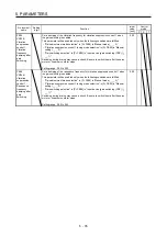
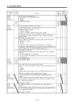
_ x _ _ Undervoltage alarm selection
Select the alarm and warning for when the bus voltage drops to the undervoltage
alarm level.
0: [AL. 10.2] regardless of servo motor speed
1: [AL. E9.1] at servo motor speed 50 r/min (50 mm/s) or less, [AL. 10.2] at over 50
r/min (50 mm/s)
0h
x _ _ _ For manufacturer setting
0h
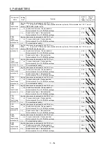
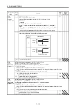
PC28
*COP7
Function
selection C-7
_ _ _ x For manufacturer setting
0h
_ _ x _
0h
_ x _ _
0h
x _ _ _ Linear scale multipoint Z-phase input function selection
When two or more reference marks exist during the full stroke of the linear encoder,
set "1".
0: Disabled
1: Enabled
This parameter setting is available with servo amplifiers with software version A5 or
later.
This digit is not available with MR-J4-03A6(-RJ) servo amplifiers.
0h
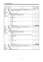
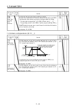
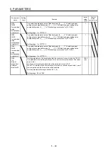
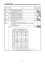
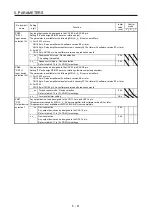
PC30
STA2
Acceleration
time constant
2
To enable the parameter, turn on STAB2 (Speed acceleration/deceleration
selection).
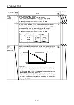
Set the acceleration time required to reach the rated speed from 0 r/min or 0 mm/s
for VC (Analog speed command) and [Pr. PC05 Internal speed command 1] to [Pr.
PC11 Internal speed command 7].
Setting range: 0 to 50000
0
[ms]
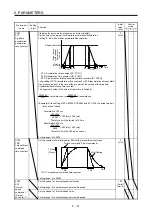
PC31
STB2
Deceleration
time constant
2
To enable the parameter, turn on STAB2 (Speed acceleration/deceleration
selection).
Set the deceleration time required to reach 0 r/min or 0 mm/s from the rated speed
for VC (Analog speed command) and [Pr. PC05 Internal speed command 1] to [Pr.
PC11 Internal speed command 7].
Setting range: 0 to 50000
0
[ms]
Содержание MR-J4-100A(-RJ)
Страница 19: ...10 MEMO ...
Страница 75: ...1 FUNCTIONS AND CONFIGURATION 1 56 MEMO ...
Страница 83: ...2 INSTALLATION 2 8 MEMO ...
Страница 159: ...3 SIGNALS AND WIRING 3 76 MEMO ...
Страница 203: ...4 STARTUP 4 44 MEMO ...
Страница 351: ...7 SPECIAL ADJUSTMENT FUNCTIONS 7 40 MEMO ...
Страница 365: ...8 TROUBLESHOOTING 8 14 MEMO ...
Страница 387: ...9 DIMENSIONS 9 22 MEMO ...
Страница 403: ...10 CHARACTERISTICS 10 16 MEMO ...
Страница 553: ...12 ABSOLUTE POSITION DETECTION SYSTEM 12 30 MEMO ...
Страница 567: ...13 USING STO FUNCTION 13 14 MEMO ...
Страница 607: ...14 COMMUNICATION FUNCTION MITSUBISHI ELECTRIC GENERAL PURPOSE AC SERVO PROTOCOL 14 40 MEMO ...
Страница 639: ...15 USING A LINEAR SERVO MOTOR 15 32 MEMO ...
Страница 767: ...18 MR J4 03A6 RJ SERVO AMPLIFIER 18 84 MEMO ...
Страница 856: ...APPENDIX App 41 ...
Страница 905: ...MEMO ...


