

6. NORMAL GAIN ADJUSTMENT
6 - 1
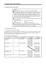
6. NORMAL GAIN ADJUSTMENT
POINT
In the torque control mode, you do not need to make gain adjustment.
Before making gain adjustment, check that your machine is not being operated
at maximum torque of the servo motor. If operated over maximum torque, the
machine may vibrate and may operate unexpectedly. In addition, make gain
adjustment with a safety margin considering characteristic differences of each
machine. It is recommended that generated torque during operation is under
90% of the maximum torque of the servo motor.
When you use a linear servo motor, replace the following words in the left to the
words in the right.
Load to motor inertia ratio
→
Load to motor mass ratio
Torque
→
Thrust
(Servo motor) speed
→
(Linear servo motor) speed
For the vibration suppression control tuning mode, the setting range of [Pr.
PB07] is limited. For the vibration suppression control tuning mode, the setting
range of [Pr. PB07] is limited. Refer to section 7.1.5 (4) for details.
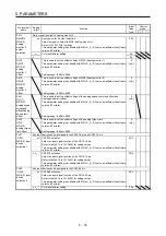
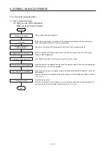
6.1 Different adjustment methods
6.1.1 Adjustment on a single servo amplifier
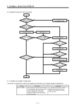
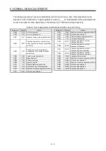
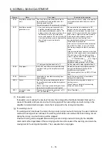
The following table shows the gain adjustment modes that can be set on a single servo amplifier. For gain
adjustment, first execute "Auto tuning mode 1". If you are not satisfied with the result of the adjustment,
execute "Auto tuning mode 2" and "Manual mode" in this order.
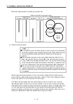
(1) Gain adjustment mode explanation
Gain adjustment mode
[Pr. PA08] setting
Estimation of load to motor
inertia ratio
Automatically set
parameters
Manually set
parameters
Auto tuning mode 1
(initial value)
_ _ _ 1
Always estimated
GD2 ([Pr. PB06])
PG1 ([Pr. PB07])
PG2 ([Pr. PB08])
VG2 ([Pr. PB09])
VIC ([Pr. PB10])
RSP ([Pr. PA09])
Auto tuning mode 2
_ _ _ 2
Fixed to [Pr. PB06] value
PG1 ([Pr. PB07])
PG2 ([Pr. PB08])
VG2 ([Pr. PB09])
VIC ([Pr. PB10])
GD2 ([Pr. PB06])
RSP ([Pr. PA09])
Manual mode
_ _ _ 3
GD2 ([Pr. PB06])
PG1 ([Pr. PB07])
PG2 ([Pr. PB08])
VG2 ([Pr. PB09])
VIC ([Pr. PB10])
2 gain adjustment mode 1
(interpolation mode)
_ _ _ 0
Always estimated
GD2 ([Pr. PB06])
PG2 ([Pr. PB08])
VG2 ([Pr. PB09])
VIC ([Pr. PB10])
PG1 ([Pr. PB07])
RSP ([Pr. PA09])
2 gain adjustment mode 2
_ _ _ 4
Fixed to [Pr. PB06] value
PG2 ([Pr. PB08])
VG2 ([Pr. PB09])
VIC ([Pr. PB10])
GD2 ([Pr. PB06])
PG1 ([Pr. PB07])
RSP ([Pr. PA09])
Содержание MR-J4-100A(-RJ)
Страница 19: ...10 MEMO ...
Страница 75: ...1 FUNCTIONS AND CONFIGURATION 1 56 MEMO ...
Страница 83: ...2 INSTALLATION 2 8 MEMO ...
Страница 159: ...3 SIGNALS AND WIRING 3 76 MEMO ...
Страница 203: ...4 STARTUP 4 44 MEMO ...
Страница 351: ...7 SPECIAL ADJUSTMENT FUNCTIONS 7 40 MEMO ...
Страница 365: ...8 TROUBLESHOOTING 8 14 MEMO ...
Страница 387: ...9 DIMENSIONS 9 22 MEMO ...
Страница 403: ...10 CHARACTERISTICS 10 16 MEMO ...
Страница 553: ...12 ABSOLUTE POSITION DETECTION SYSTEM 12 30 MEMO ...
Страница 567: ...13 USING STO FUNCTION 13 14 MEMO ...
Страница 607: ...14 COMMUNICATION FUNCTION MITSUBISHI ELECTRIC GENERAL PURPOSE AC SERVO PROTOCOL 14 40 MEMO ...
Страница 639: ...15 USING A LINEAR SERVO MOTOR 15 32 MEMO ...
Страница 767: ...18 MR J4 03A6 RJ SERVO AMPLIFIER 18 84 MEMO ...
Страница 856: ...APPENDIX App 41 ...
Страница 905: ...MEMO ...


