


6. NORMAL GAIN ADJUSTMENT
6 - 30
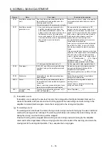
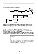
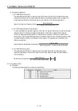
3) [Pr. PB08 Position loop gain]
This parameter determines the response level to a disturbance to the position control loop.
Increasing the value increases the response level to the disturbance, but a too high value will
increase vibration of the mechanical system.
Position loop gain guideline
≤
(1 + Load to motor inertia ratio)
Speed loop gain
×
8
1
4
1 to
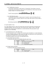
4) [Pr. PB07 Model loop gain]
This parameter determines the response level to a position command. Increasing the value
improves trackability to a position command, but a too high value will make overshoot liable to
occur at settling.
Model loop gain guideline
≤
(1 + Load to motor inertia ratio)
Speed loop gain
×
8
1
4
1 to
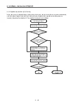
6.5 2 gain adjustment mode
The 2 gain adjustment mode is used to match the position loop gains of the axes when performing the
interpolation operation of servo motors of two or more axes for an X-Y table or the like. In this mode,
manually set the model loop gain that determines command trackability. Other parameters for gain
adjustment are set automatically.
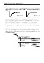
(1) 2 gain adjustment mode 1 (interpolation mode)
The 2 gain adjustment mode 1 manually set the model loop gain that determines command trackability.
The mode constantly estimates the load to motor inertia ratio, and automatically set other parameters for
gain adjustment to optimum gains using auto tuning response.
The following parameters are used for 2 gain adjustment mode 1.
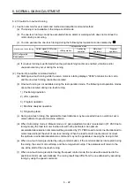
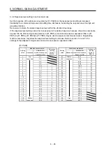
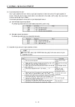
(a) Automatically adjusted parameter
The following parameters are automatically adjusted by auto tuning.
Parameter Symbol
Name
PB06
GD2
Load to motor inertia ratio
PB08
PG2
Position loop gain
PB09
VG2
Speed loop gain
PB10
VIC
Speed integral compensation
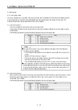
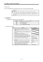
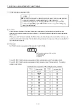
(b) Manually adjusted parameter
The following parameters are adjustable manually.
Parameter Symbol
Name
PA09
RSP
Auto tuning response
PB07
PG1
Model loop gain
Содержание MR-J4-100A(-RJ)
Страница 19: ...10 MEMO ...
Страница 75: ...1 FUNCTIONS AND CONFIGURATION 1 56 MEMO ...
Страница 83: ...2 INSTALLATION 2 8 MEMO ...
Страница 159: ...3 SIGNALS AND WIRING 3 76 MEMO ...
Страница 203: ...4 STARTUP 4 44 MEMO ...
Страница 351: ...7 SPECIAL ADJUSTMENT FUNCTIONS 7 40 MEMO ...
Страница 365: ...8 TROUBLESHOOTING 8 14 MEMO ...
Страница 387: ...9 DIMENSIONS 9 22 MEMO ...
Страница 403: ...10 CHARACTERISTICS 10 16 MEMO ...
Страница 553: ...12 ABSOLUTE POSITION DETECTION SYSTEM 12 30 MEMO ...
Страница 567: ...13 USING STO FUNCTION 13 14 MEMO ...
Страница 607: ...14 COMMUNICATION FUNCTION MITSUBISHI ELECTRIC GENERAL PURPOSE AC SERVO PROTOCOL 14 40 MEMO ...
Страница 639: ...15 USING A LINEAR SERVO MOTOR 15 32 MEMO ...
Страница 767: ...18 MR J4 03A6 RJ SERVO AMPLIFIER 18 84 MEMO ...
Страница 856: ...APPENDIX App 41 ...
Страница 905: ...MEMO ...


