
APPENDIX
App. - 68
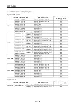
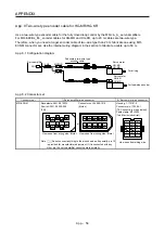
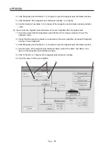
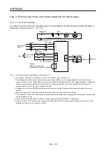
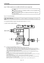
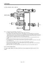
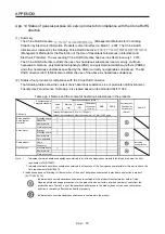
(2) MR-J4-200A-RJ to MR-J4-22KA-RJ
ALM
DOCOM
CN1
RA1
L11
L21
MC
MC
CN1
EM2
CN8
MCCB
SK
(Note 9)
+
-
SON
DICOM
L1
L2
L3
N-
(Note 2)
24 V DC (Note 6)
Malfunction
Forced stop 2
(Note 2)
(Note 4)
Main circuit power supply
24 V DC (Note 6)
Servo-on
Malfunction
RA1
MC (Note 3)
24 V DC (Note 7, 8)
3-phase or 1-phase
200 V AC to 240 V AC
Servo amplifier
Emergency stop switch
(Note 1)
AC/DC
Converter
(283 V DC to
340 V DC)
(Note 5)
Short-circuit connector
(packed with the servo
amplifier)
ON
OFF
Note 1. For the power supply specifications, refer to section 1.3.
2. This diagram shows sink I/O interface. For source I/O interface, refer to section 3.9.3.
3. Use a magnetic contactor with an operation delay time (interval between current being applied to the coil until closure of
contacts) of 80 ms or less (160 ms or less for 5 kW or more). Depending on the main circuit voltage and operation pattern, bus
voltage decreases, and that may cause the forced stop deceleration to shift to the dynamic brake deceleration. When dynamic
brake deceleration is not required, delay the time to turn off the magnetic contactor.
4. Configure a circuit to turn off EM2 when the main circuit power is turned off to prevent an unexpected restart of the servo
amplifier.
5. When not using the STO function, attach the short-circuit connector came with a servo amplifier.
6. The illustration of the 24 V DC power supply is divided between input signal and output signal for convenience. However, they
can be configured by one.
7. Driving the on switch and off switch with the DC power supply meets IEC/EN 60204-1 requirements.
8. Do not use the 24 V DC interface power supply for the magnetic contactor DC power supply. Always use the power supply
designed exclusively for the magnetic contactor.
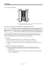
9. When wires used for L11 and L21 are thinner than wires used for L1/L2/L3, and N-, use a fuse. (Refer to app. 13.4.)
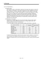
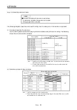
App. 13.2 Power supply capacity
The power supply capacity is the same as that for the AC power supply input. Refer to section 10.2 for
details.
Содержание MR-J4-100A(-RJ)
Страница 19: ...10 MEMO ...
Страница 75: ...1 FUNCTIONS AND CONFIGURATION 1 56 MEMO ...
Страница 83: ...2 INSTALLATION 2 8 MEMO ...
Страница 159: ...3 SIGNALS AND WIRING 3 76 MEMO ...
Страница 203: ...4 STARTUP 4 44 MEMO ...
Страница 351: ...7 SPECIAL ADJUSTMENT FUNCTIONS 7 40 MEMO ...
Страница 365: ...8 TROUBLESHOOTING 8 14 MEMO ...
Страница 387: ...9 DIMENSIONS 9 22 MEMO ...
Страница 403: ...10 CHARACTERISTICS 10 16 MEMO ...
Страница 553: ...12 ABSOLUTE POSITION DETECTION SYSTEM 12 30 MEMO ...
Страница 567: ...13 USING STO FUNCTION 13 14 MEMO ...
Страница 607: ...14 COMMUNICATION FUNCTION MITSUBISHI ELECTRIC GENERAL PURPOSE AC SERVO PROTOCOL 14 40 MEMO ...
Страница 639: ...15 USING A LINEAR SERVO MOTOR 15 32 MEMO ...
Страница 767: ...18 MR J4 03A6 RJ SERVO AMPLIFIER 18 84 MEMO ...
Страница 856: ...APPENDIX App 41 ...
Страница 905: ...MEMO ...


