

11. OPTIONS AND PERIPHERAL EQUIPMENT
11 - 112
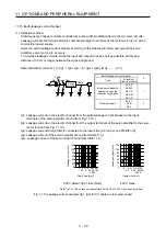
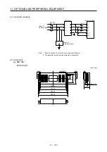
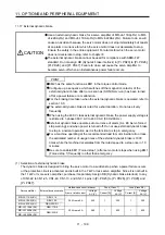
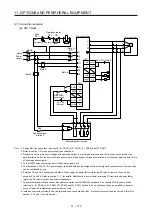
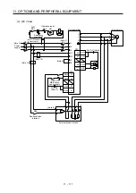
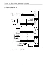
Note 1. Assign DB (Dynamic brake interlock) in [Pr. PD23] to [Pr. PD26], [Pr. PD28], and [Pr. PD47].
2. For power supply specifications, refer to section 1.3.
3. Depending on the main circuit voltage and operation pattern, bus voltage decreases, and that may cause the forced stop
deceleration to shift to the dynamic brake deceleration. When dynamic brake deceleration is not required, slow the time to
turn off the magnetic contactor.
4. Turn off EM2 when the main power circuit power supply is off.
5. The illustration of the 24 V DC power supply is divided between input signal and output signal for convenience. However, they
can be configured by one.
6. Between P3 and P4 is connected by default. When using the power factor improving DC reactor, remove the short bar
between P3 and P4. Refer to section 11.11 for details. Additionally, a power factor improving DC reactor and power factor
improving AC reactor cannot be used simultaneously.
7. Stepdown transformer is required when the coil voltage of the magnetic contactor is 200 V class.
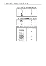
8. The power supply voltage of the inside magnet contactor for 400 V class external dynamic brake DBU-11K-4 and DBU-22K-4
is restricted as follows. When using these external dynamic brakes, use them within the range of the power supply.
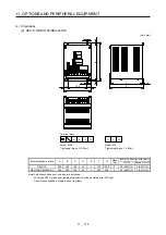
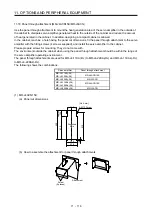
External dynamic brake
Power supply voltage
DBU-11K-4
DBU-22K-4
1-phase 380 V AC to 463 V AC, 50
Hz/60 Hz
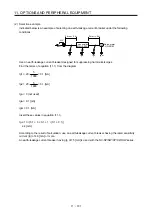
9. The external dynamic brake cannot be used for compliance with SEMI-F47 standard. Do not assign DB (Dynamic brake
interlock) in [Pr. PD23] to [Pr. PD26], [Pr. PD28], and [Pr. PD47]. Failure to do so will cause the servo amplifier to become
servo-off when an instantaneous power failure occurs.
10. Install an overcurrent protection device (molded-case circuit breaker, fuse, or others) to protect the branch circuit. (Refer to
section 11.10 and (1) in this section.)
Содержание MR-J4-100A(-RJ)
Страница 19: ...10 MEMO ...
Страница 75: ...1 FUNCTIONS AND CONFIGURATION 1 56 MEMO ...
Страница 83: ...2 INSTALLATION 2 8 MEMO ...
Страница 159: ...3 SIGNALS AND WIRING 3 76 MEMO ...
Страница 203: ...4 STARTUP 4 44 MEMO ...
Страница 351: ...7 SPECIAL ADJUSTMENT FUNCTIONS 7 40 MEMO ...
Страница 365: ...8 TROUBLESHOOTING 8 14 MEMO ...
Страница 387: ...9 DIMENSIONS 9 22 MEMO ...
Страница 403: ...10 CHARACTERISTICS 10 16 MEMO ...
Страница 553: ...12 ABSOLUTE POSITION DETECTION SYSTEM 12 30 MEMO ...
Страница 567: ...13 USING STO FUNCTION 13 14 MEMO ...
Страница 607: ...14 COMMUNICATION FUNCTION MITSUBISHI ELECTRIC GENERAL PURPOSE AC SERVO PROTOCOL 14 40 MEMO ...
Страница 639: ...15 USING A LINEAR SERVO MOTOR 15 32 MEMO ...
Страница 767: ...18 MR J4 03A6 RJ SERVO AMPLIFIER 18 84 MEMO ...
Страница 856: ...APPENDIX App 41 ...
Страница 905: ...MEMO ...


