


3. SIGNALS AND WIRING
3 - 63
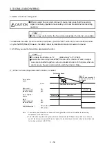
3.9.2 Detailed explanation of interfaces
This section provides the details of the I/O signal interfaces (refer to the I/O division in the table) given in
section 3.5. Refer to this section and make connection with the external device.
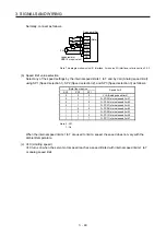
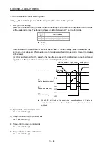
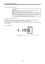
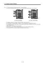
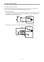
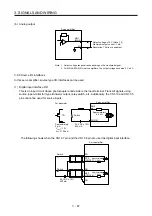
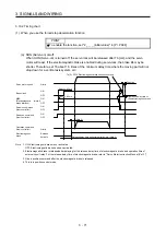
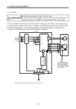
(1) Digital input interface DI-1
This is an input circuit whose photocoupler cathode side is the input terminal. Transmit signals from sink
(open-collector) type transistor output, relay switch, etc. The following is a connection diagram for sink
input. Refer to section 3.9.3 for source input.
Approximately
5 mA
TR
24 V DC ± 10%
500 mA
Switch
For transistor
EM2,
etc.
Servo amplifier
DICOM
V
CES
1.0 V
I
CEO
100 µA
Approximately
6.2 k
Ω
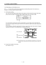
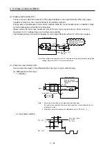
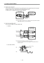
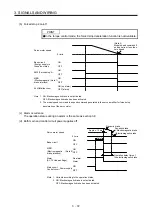
The following is for when CN1-10 pin and CN1-35 pin are used as digital input interfaces.
Approx. 1.2 k
Ω
Servo amplifier
24 V DC ± 10%
300 mA
OPC
CN1-10, CN1-35
DOCOM
SD
10 m or less
V
CES
≤
1.0 V
I
CEO
≤
100
μ
A
Approx. 20 mA
Содержание MR-J4-100A(-RJ)
Страница 19: ...10 MEMO ...
Страница 75: ...1 FUNCTIONS AND CONFIGURATION 1 56 MEMO ...
Страница 83: ...2 INSTALLATION 2 8 MEMO ...
Страница 159: ...3 SIGNALS AND WIRING 3 76 MEMO ...
Страница 203: ...4 STARTUP 4 44 MEMO ...
Страница 351: ...7 SPECIAL ADJUSTMENT FUNCTIONS 7 40 MEMO ...
Страница 365: ...8 TROUBLESHOOTING 8 14 MEMO ...
Страница 387: ...9 DIMENSIONS 9 22 MEMO ...
Страница 403: ...10 CHARACTERISTICS 10 16 MEMO ...
Страница 553: ...12 ABSOLUTE POSITION DETECTION SYSTEM 12 30 MEMO ...
Страница 567: ...13 USING STO FUNCTION 13 14 MEMO ...
Страница 607: ...14 COMMUNICATION FUNCTION MITSUBISHI ELECTRIC GENERAL PURPOSE AC SERVO PROTOCOL 14 40 MEMO ...
Страница 639: ...15 USING A LINEAR SERVO MOTOR 15 32 MEMO ...
Страница 767: ...18 MR J4 03A6 RJ SERVO AMPLIFIER 18 84 MEMO ...
Страница 856: ...APPENDIX App 41 ...
Страница 905: ...MEMO ...


