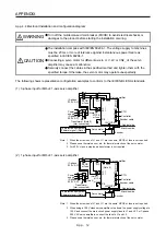
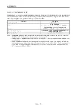

APPENDIX
App. - 6
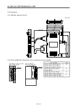
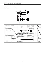
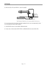
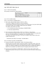
(1) Peripheral device and power wiring
The followings are selected based on IEC/EN 61800-5-1, UL 508C, and CSA C22.2 No. 14.
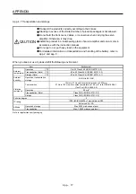
(a) Power Wiring (local wiring and crimping tool)
Use only copper wires or copper bus bars for wiring. The following table shows the stranded wire
sizes [AWG] and the crimp terminal symbols rated at 75 °C/60 °C.
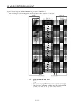
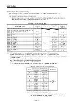
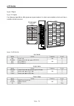
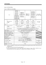
Table app. 1 Recommended wires
Servo amplifier (Note 7)
75 °C/60 °C stranded wire [AWG] (Note 2)
L1/L2/L3
L11/L21 P+/C
U/V/W/
(Note 3)
MR-J4-03A6/MR-J4W2-0303B6
19/- (Note 5)
19/- (Note 6)
MR-J4-10_(1)/MR-J4-20_(1)/MR-J4-40_(1)/MR-J4-60_(4)/
MR-J4-70_/MR-J4-100_(4)/MR-J4-200_(4) (T)/
MR-J4-350_4
14/14
14/14 14/14
14/14
MR-J4-200_ (S)
12/12
MR-J4-350_
12/12
MR-J4-500_ (Note 1)
10: a/10: a
14: c/14: c
10: b/10: b
MR-J4-700_ (Note 1)
8: b/8: b
12: a/12: a
8: b/8: b
MR-J4-11K_ (Note 1)
6: d/4: f
12: e/12: e
4: f/4: f
MR-J4-15K_ (Note 1)
4: f/3: f
10: e/10: e
3: g/2: g
MR-J4-22K_ (Note 1)
1: h/-: -
14: c/14: c
10: i/10: i
1: j/-: -
MR-J4-500_4 (Note 1)
14: c/14: c
14: c/14: c
12: a/10: a
MR-J4-700_4 (Note 1)
12: a/12: a
10: a/10: a
MR-J4-11K_4 (Note 1)
10: e/10: e
14: k/14: k
8: l/8: l
MR-J4-15K_4 (Note 1)
8: l/8: l
12: e/12: e
6: d/4: d
MR-J4-22K_4 (Note 1)
6: m/4: m
12: i/12: i
6: n/4: n
MR-J4W_-_B
14/14 (Note 4)
14/14
14/14 14/14
Note 1. To connect these models to a terminal block, be sure to use the screws that come with the terminal block.
2.
Alphabets in the table indicate crimping tools. Refer to table app. 2 for the crimp terminals and crimping tools.
3. Select wire sizes depending on the rated output of the servo motors. The values in the table are sizes based on rated output of
the servo amplifiers.
4. Use the crimp terminal c for the PE terminal of the servo amplifier.
5. This value is of 24/0/PM/ for MR-J4-03A6 and MR-J4W2-0303B6.
6. This value is of U/V/W/E for MR-J4-03A6 and MR-J4W2-0303B6.
7. "(S)" means 1-phase 200 V AC power input and "(T)" means 3-phase 200 V AC power input in the table.
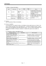
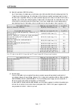
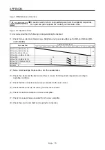
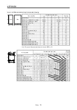
Table app. 2 Recommended crimp terminals
Symbol
Servo amplifier-side crimp terminals
Manufacturer
Crimp terminal
(Note 2)
Applicable tool
a FVD5.5-4 YNT-1210S
b (Note 1)
8-4NS
YHT-8S
c FVD2-4 YNT-1614
d FVD14-6 YF-1
e FVD5.5-6 YNT-1210S
f FVD22-6 YF-1
JST
(J.S.T. Mfg. Co.,
Ltd.)
g FVD38-6 YF-1
h R60-8 YF-1
i FVD5.5-8
YNT-1210S
j CB70-S8 YF-1
k FVD2-6 YNT-1614
l FVD8-6 YF-1
m FVD14-8
YF-1
n FVD22-8 YF-1
Note 1. Coat the crimping part with an insulation tube.
2. Some crimp terminals may not be mounted depending on the size. Make sure to
use the recommended ones or equivalent ones.
Содержание MR-J4-100A(-RJ)
Страница 19: ...10 MEMO ...
Страница 75: ...1 FUNCTIONS AND CONFIGURATION 1 56 MEMO ...
Страница 83: ...2 INSTALLATION 2 8 MEMO ...
Страница 159: ...3 SIGNALS AND WIRING 3 76 MEMO ...
Страница 203: ...4 STARTUP 4 44 MEMO ...
Страница 351: ...7 SPECIAL ADJUSTMENT FUNCTIONS 7 40 MEMO ...
Страница 365: ...8 TROUBLESHOOTING 8 14 MEMO ...
Страница 387: ...9 DIMENSIONS 9 22 MEMO ...
Страница 403: ...10 CHARACTERISTICS 10 16 MEMO ...
Страница 553: ...12 ABSOLUTE POSITION DETECTION SYSTEM 12 30 MEMO ...
Страница 567: ...13 USING STO FUNCTION 13 14 MEMO ...
Страница 607: ...14 COMMUNICATION FUNCTION MITSUBISHI ELECTRIC GENERAL PURPOSE AC SERVO PROTOCOL 14 40 MEMO ...
Страница 639: ...15 USING A LINEAR SERVO MOTOR 15 32 MEMO ...
Страница 767: ...18 MR J4 03A6 RJ SERVO AMPLIFIER 18 84 MEMO ...
Страница 856: ...APPENDIX App 41 ...
Страница 905: ...MEMO ...


