


1. FUNCTIONS AND CONFIGURATION
1 - 15
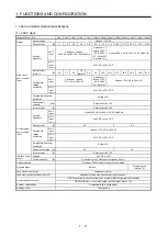
Model:
MR-J4-_(-RJ)
60A4 100A4 200A4 350A4 500A4 700A4 11KA4 15KA4 22KA4
Safety
performance
Standards certified by CB
(Note 9)
EN ISO 13849-1 Category 3 PL e, IEC 61508 SIL 3, EN 62061 SIL CL3, and EN 61800-5-2
Response performance
8 ms or less (STO input off
→
energy shut off)
Test pulse input (STO)
(Note 2)
Test pulse interval: 1 Hz to 25 Hz
Test pulse off time: Up to 1 ms
Mean time to dangerous
failure (MTTFd)
MTTFd
≥
100 [years] (314a)
Diagnostic coverage (DC)
DC = Medium, 97.6 [%]
Average probability of
dangerous failures per hour
(PFH)
PFH = 6.4 × 10
-9
[1/h]
Compliance
with standards
CE marking
LVD: EN 61800-5-1
EMC: EN 61800-3
MD: EN ISO 13849-1, EN 61800-5-2, EN 62061
UL standard
UL 508C
Structure (IP rating)
Natural cooling, open
(IP20)
Force cooling, open
(IP20)
Force cooling, open (IP20) (Note 3)
Close
mounting
Impossible
Environment
Ambient
temperature
Operation
0
˚
C to 55
˚
C (non-freezing)
Storage
-20
˚
C to 65
˚
C (non-freezing)
Ambient
humidity
Operation
5 %RH to 90 %RH (non-condensing)
Storage
Ambience
Indoors (no direct sunlight),
free from corrosive gas, flammable gas, oil mist, dust, and dirt
Altitude
2000 m or less above sea level (Note 10)
Vibration resistance
5.9 m/s
2
, at 10 Hz to 55 Hz (directions of X, Y and Z axes)
Mass
[kg]
1.7 2.1
3.6 4.3 6.5
13.4
18.2
Note 1. 0.5 A is the value applicable when all I/O signals are used. The current capacity can be decreased by reducing the number of
I/O points.
2. Test pulse is a signal which instantaneously turns off a signal to the servo amplifier at a constant period for external circuit to
self-diagnose.
3. Except for the terminal block.
4. 1 Mpulse/s or lower commands are supported in the initial setting. When inputting commands over 1 Mpulse/s and 4
Mpulses/s or lower, change the setting in [Pr. PA13].
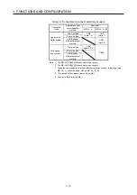
5. MR-J4-_A4 servo amplifier is compatible only with two-wire type. MR-J4-_A4-RJ servo amplifier is compatible with two-wire
type, four-wire type, and A/B/Z-phase differential output method. Refer to table 1.1 for details.
6. Use an external dynamic brake for this servo amplifier. Failure to do so will cause an accident because the servo motor does
not stop immediately but coasts at emergency stop. Ensure the safety in the entire equipment.
7. The external dynamic brake cannot be used for compliance with SEMI-F47 standard. Do not assign DB (Dynamic brake
interlock) in [Pr. PD23] to [Pr. PD26], [Pr. PD28], and [Pr. PD47]. Failure to do so will cause the servo amplifier to become
servo-off when an instantaneous power failure occurs.
8. RS-485 communication is available with servo amplifiers manufactured in November 2014 or later.
9. The safety level depends on the setting value of [Pr. PF18 STO diagnosis error detection time] and whether STO input
diagnosis by TOFB output is performed or not. For details, refer to the Function column of [Pr. PF18] in section 5.2.6.
10. Follow the restrictions in section 2.6 when using this product at altitude exceeding 1000 m and up to 2000 m above sea level.
Содержание MR-J4-100A(-RJ)
Страница 19: ...10 MEMO ...
Страница 75: ...1 FUNCTIONS AND CONFIGURATION 1 56 MEMO ...
Страница 83: ...2 INSTALLATION 2 8 MEMO ...
Страница 159: ...3 SIGNALS AND WIRING 3 76 MEMO ...
Страница 203: ...4 STARTUP 4 44 MEMO ...
Страница 351: ...7 SPECIAL ADJUSTMENT FUNCTIONS 7 40 MEMO ...
Страница 365: ...8 TROUBLESHOOTING 8 14 MEMO ...
Страница 387: ...9 DIMENSIONS 9 22 MEMO ...
Страница 403: ...10 CHARACTERISTICS 10 16 MEMO ...
Страница 553: ...12 ABSOLUTE POSITION DETECTION SYSTEM 12 30 MEMO ...
Страница 567: ...13 USING STO FUNCTION 13 14 MEMO ...
Страница 607: ...14 COMMUNICATION FUNCTION MITSUBISHI ELECTRIC GENERAL PURPOSE AC SERVO PROTOCOL 14 40 MEMO ...
Страница 639: ...15 USING A LINEAR SERVO MOTOR 15 32 MEMO ...
Страница 767: ...18 MR J4 03A6 RJ SERVO AMPLIFIER 18 84 MEMO ...
Страница 856: ...APPENDIX App 41 ...
Страница 905: ...MEMO ...


