

5. PARAMETERS
5 - 47
No./symbol/
name
Setting
digit
Function
Initial
value
[unit]
Control
mode
P S T
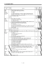
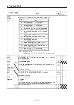
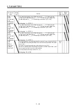
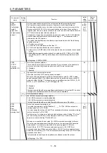
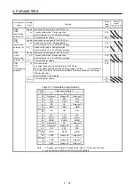
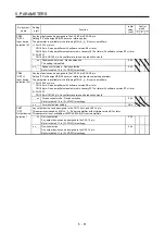
PC22
*COP1
Function
selection C-1
_ _ _ x For manufacturer setting
0h
_ _ x _
0h
_ x _ _
0h
x _ _ _ Encoder cable communication method selection
Select the encoder cable communication method.
0: Two-wire type
1: Four-wire type
When using an encoder of A/B/Z-phase differential output method, set "0".
If the setting is incorrect, [AL. 16 Encoder initial communication error 1] or [AL. 20
Encoder normal communication error 1] occurs. Setting "1" will trigger [AL. 37] while
"Fully closed loop control mode (_ _ 1 _)" is selected in [Pr. PA01] (except MR-J4-
_A_-RJ).
For MR-J4-03A6(-RJ) servo amplifiers, this digit cannot be used when a setting
value other than the initial value is set. Also, it does not comply with encoders of
A/B/Z-phase differential output method.
0h
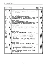
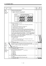
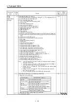
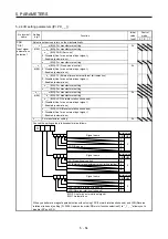
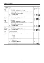
PC23
*COP2
Function
selection C-2
_ _ _ x Servo-lock selection at speed control stop
Select the servo-lock selection at speed control stop.
In the speed control mode, the servo motor shaft can be locked to prevent the shaft
from being moved by an external force.
0: Enabled (servo-lock)
The operation to maintain the stop position is performed.
1: Disabled (no servo-lock)
The stop position is not maintained.
The control to make the speed 0 r/min or 0 mm/s is performed.
0h
_ _ x _ For manufacturer setting
0h
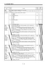
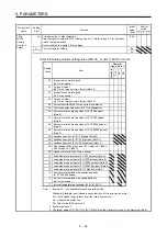
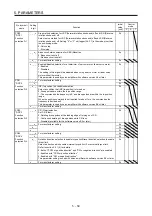
_ x _ _ VC/VLA voltage averaging selection
Select the VC/VLA voltage average.
Set the filtering time when VC (Analog speed command) or VLA (Analog speed limit)
is imported.
Set "0" to vary the speed to voltage fluctuation in real time. Increase the set value to
vary the speed slower to voltage fluctuation.
0h
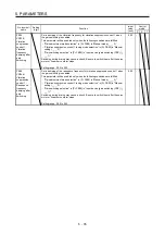
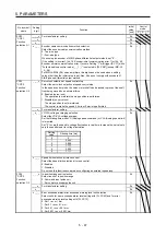
Setting
value
Filtering time [ms]
0
0
1
0.444
2
0.888
3
1.777
4
3.555
5
7.111
x _ _ _ Speed limit selection at torque control
Select the speed limit selection at torque control.
0: Enabled
1: Disabled
Do not use this function except when configuring an external speed loop.
0h
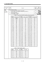
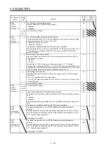
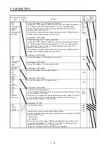
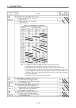
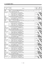
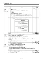
PC24
*COP3
Function
selection C-3
_ _ _ x In-position range unit selection
Select a unit of in-position range.
0: Command input pulse unit
1: Servo motor encoder pulse unit
0h
_ _ x _ For manufacturer setting
0h
_ x _ _
0h
x _ _ _ Error excessive alarm/error excessive warning level unit selection
Select units for error excessive alarm level setting with [Pr. PC43] and for error
excessive warning level setting with [Pr. PC73].
0: Per 1 rev or 1 mm
1: Per 0.1 rev or 0.1 mm
2: Per 0.01 rev or 0.01 mm
3: Per 0.001 rev or 0.001 mm
0h
Содержание MR-J4-100A(-RJ)
Страница 19: ...10 MEMO ...
Страница 75: ...1 FUNCTIONS AND CONFIGURATION 1 56 MEMO ...
Страница 83: ...2 INSTALLATION 2 8 MEMO ...
Страница 159: ...3 SIGNALS AND WIRING 3 76 MEMO ...
Страница 203: ...4 STARTUP 4 44 MEMO ...
Страница 351: ...7 SPECIAL ADJUSTMENT FUNCTIONS 7 40 MEMO ...
Страница 365: ...8 TROUBLESHOOTING 8 14 MEMO ...
Страница 387: ...9 DIMENSIONS 9 22 MEMO ...
Страница 403: ...10 CHARACTERISTICS 10 16 MEMO ...
Страница 553: ...12 ABSOLUTE POSITION DETECTION SYSTEM 12 30 MEMO ...
Страница 567: ...13 USING STO FUNCTION 13 14 MEMO ...
Страница 607: ...14 COMMUNICATION FUNCTION MITSUBISHI ELECTRIC GENERAL PURPOSE AC SERVO PROTOCOL 14 40 MEMO ...
Страница 639: ...15 USING A LINEAR SERVO MOTOR 15 32 MEMO ...
Страница 767: ...18 MR J4 03A6 RJ SERVO AMPLIFIER 18 84 MEMO ...
Страница 856: ...APPENDIX App 41 ...
Страница 905: ...MEMO ...


