


1. FUNCTIONS AND CONFIGURATION
1 - 34
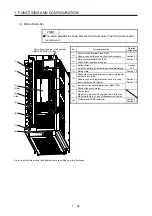
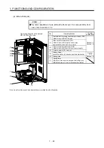
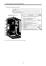
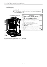
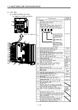
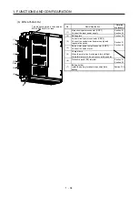
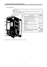
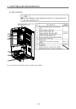
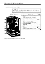
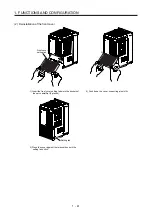
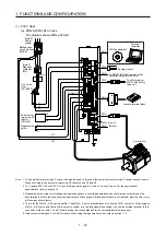
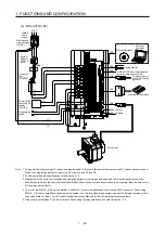
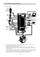
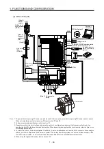
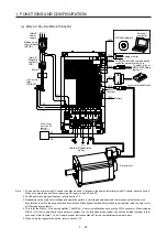
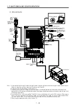
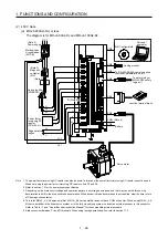
(b) MR-J4-350A4(-RJ)
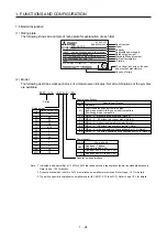
(1)
(3)
(2)
Side
(4)
(5)
(6)
(7)
The broken line area is the same as
MR-J4-200A4(-RJ) or less.
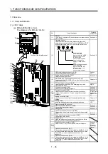
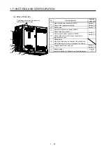
No. Name/Application
Detailed
explanation
(1)
Main circuit power connector (CNP1)
Connect the input power supply.
Section 3.1
Section 3.3
(2)
Rating plate
Section 1.6
(3)
Control circuit power connector (CNP2)
Connect the control circuit power supply and
regenerative option.
Section 3.1
Section 3.3
(4)
Servo motor power output connector (CNP3)
Connect the servo motor.
(5)
Charge lamp
When the main circuit is charged, this will light.
While this lamp is lit, do not reconnect the cables.
(6)
Protective earth (PE) terminal
Section 3.1
Section 3.3
(7)
Battery holder
Install the battery for absolute position data
backup.
Section 12.2
Содержание MR-J4-100A(-RJ)
Страница 19: ...10 MEMO ...
Страница 75: ...1 FUNCTIONS AND CONFIGURATION 1 56 MEMO ...
Страница 83: ...2 INSTALLATION 2 8 MEMO ...
Страница 159: ...3 SIGNALS AND WIRING 3 76 MEMO ...
Страница 203: ...4 STARTUP 4 44 MEMO ...
Страница 351: ...7 SPECIAL ADJUSTMENT FUNCTIONS 7 40 MEMO ...
Страница 365: ...8 TROUBLESHOOTING 8 14 MEMO ...
Страница 387: ...9 DIMENSIONS 9 22 MEMO ...
Страница 403: ...10 CHARACTERISTICS 10 16 MEMO ...
Страница 553: ...12 ABSOLUTE POSITION DETECTION SYSTEM 12 30 MEMO ...
Страница 567: ...13 USING STO FUNCTION 13 14 MEMO ...
Страница 607: ...14 COMMUNICATION FUNCTION MITSUBISHI ELECTRIC GENERAL PURPOSE AC SERVO PROTOCOL 14 40 MEMO ...
Страница 639: ...15 USING A LINEAR SERVO MOTOR 15 32 MEMO ...
Страница 767: ...18 MR J4 03A6 RJ SERVO AMPLIFIER 18 84 MEMO ...
Страница 856: ...APPENDIX App 41 ...
Страница 905: ...MEMO ...


