

11. OPTIONS AND PERIPHERAL EQUIPMENT
11 - 25
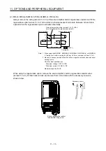
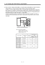
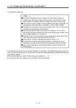
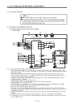
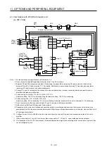
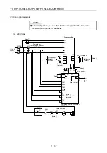
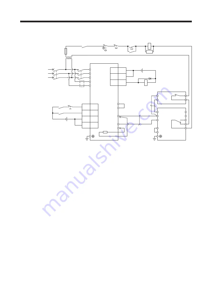
2) 400 V class
Emergency stop switch
Servo amplifier
(Note 9)
MC
MCCB
(Note 1)
Power
supply
L1
L2
L3
L11
L21
ALM
RA1
OFF
MC
ON
MC
SK
P3
P4
(Note 3)
P+
N-
C
(Note 2)
(Note 7)
(Note 11)
N/-
P/+
BUE
SD
PR
B
C
A
SD
MSG
(Note 4)
(Note 6)
FR-BU2-H
FR-BR-H
P
PR
TH2
TH1
(Note 5)
(Note 8)
48
ALM
EM2
42
24 V DC (Note 12)
46
DICOM
DOCOM
47
DOCOM
15
SON
20
DICOM
21
CN1
RA1
(Note 10)
Main circuit power supply
24 V DC
(Note 12)
Step-down
transformer
CN1
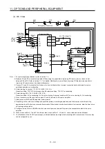
Note 1. For the power supply specifications, refer to section 1.3.
2. For the servo amplifier of 5 kW and 7 kW, always disconnect the lead wire of built-in regenerative resistor, which is connected
to P+ and C terminals. For the servo amplifier of 11 kW to 22 kW, do not connect a supplied regenerative resistor to the P+
and C terminals.
3. Between P3 and P4 is connected by default. When using the power factor improving DC reactor, remove the short bar
between P3 and P4. Refer to section 11.11 for details. Additionally, a power factor improving DC reactor and power factor
improving AC reactor cannot be used simultaneously.
4. Connect P/+ and N/- terminals of the brake unit to a correct destination. Incorrect connection destination results in servo
amplifier and brake unit malfunction.
5. Contact rating: 1b contact, 110 V AC, 5 A/220 V AC, 3 A
Normal condition: TH1-TH2 is conducting. Abnormal condition: TH1-TH2 is not conducting.
6. Contact rating: 230 V AC, 0.3 A/30 V DC, 0.3 A
Normal condition: B-C is conducting./A-C is not conducting. Abnormal condition: B-C is not conducting./A-C is conducting.
7. Do not connect more than one cable to each P+ and N- terminals of the servo amplifier.
8.
Always connect BUE and SD terminals. (factory-wired)
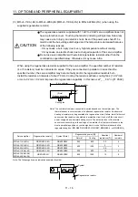
9. Depending on the main circuit voltage and operation pattern, bus voltage decreases, and that may cause the forced stop
deceleration to shift to the dynamic brake deceleration. When dynamic brake deceleration is not required, slow the time to turn
off the magnetic contactor.
10. Configure a circuit to turn off EM2 when the main circuit power is turned off to prevent an unexpected restart of the servo
amplifier.
11. When wires used for L11 and L21 are thinner than wires used for L1, L2, and L3, use a molded-case circuit breaker.
12. The illustration of the 24 V DC power supply is divided between input signal and output signal for convenience. However, they
can be configured by one.
Содержание MR-J4-100A(-RJ)
Страница 19: ...10 MEMO ...
Страница 75: ...1 FUNCTIONS AND CONFIGURATION 1 56 MEMO ...
Страница 83: ...2 INSTALLATION 2 8 MEMO ...
Страница 159: ...3 SIGNALS AND WIRING 3 76 MEMO ...
Страница 203: ...4 STARTUP 4 44 MEMO ...
Страница 351: ...7 SPECIAL ADJUSTMENT FUNCTIONS 7 40 MEMO ...
Страница 365: ...8 TROUBLESHOOTING 8 14 MEMO ...
Страница 387: ...9 DIMENSIONS 9 22 MEMO ...
Страница 403: ...10 CHARACTERISTICS 10 16 MEMO ...
Страница 553: ...12 ABSOLUTE POSITION DETECTION SYSTEM 12 30 MEMO ...
Страница 567: ...13 USING STO FUNCTION 13 14 MEMO ...
Страница 607: ...14 COMMUNICATION FUNCTION MITSUBISHI ELECTRIC GENERAL PURPOSE AC SERVO PROTOCOL 14 40 MEMO ...
Страница 639: ...15 USING A LINEAR SERVO MOTOR 15 32 MEMO ...
Страница 767: ...18 MR J4 03A6 RJ SERVO AMPLIFIER 18 84 MEMO ...
Страница 856: ...APPENDIX App 41 ...
Страница 905: ...MEMO ...


