Operation manual - EN
www.atmos.eu
EN - 189
ACD03/04
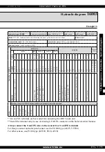
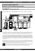
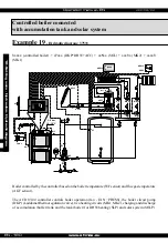
Hydraulic diagram:
37003
Example 23
Hydraulic diagram:
37033
3
xxxx (controlled boiler) x
7
xxx (DKP+DHW+ACC) xx
0
xx (none)
xxx
0
x (none)
xxxx
3
(MK1)
Boiler:
DC18GD - gasification boiler (controlled)
Boiler circui
t: DKP boiler circuit pump (Laddomat pump)
Accumulation tank:
YES
Domestic hot water:
YES (e.g. standard tank 160 L)
Heating circuits:
1 mixed equithermal (MK)
External heating:
YES - heat pump (electric heating EHP)
Contr
oller
ACD
03/04
OUTPUTS
INPUTS
Communi-
cation
Terminal / Position
Boiler
DHW
Circuit 1
Circuit 2
Circuit 3
66 (67, 68)
65 + 66
65
70
69
59 - 61
62 - 64
53 - 55
40
41
4, 6
5 - 6
7 - 8
9 - 10
11 - 12
13 - 14
15 - 16
17 - 18
19 - 20
21 - 22
27 - 30
L (N, PE)
IN L
+ L
IN L
FAN L
VA
1
DKP
SLP
MKP1
MK1 LA
MK1 LB
MKP2
MK2 LA
MK2 LB
VA3 LA
VA4 LB
AF
WF
SF
VF1
VF2
AGF
PF
VI1
VI2
VI3
VI4
VI5
12V
/
A / B / GND
12V
/
A / B / GND
Function
Controller power supply - L
(N, PE)
** Contact bridge
Fan power supply - F
AN L
Boiler fan - F
AN
Electric heating of the accumulation tank - EHP
-
Boiler pump - DKP
DHW
pump - SLP
Circuit 1 pump - MKP1
Servo circuit 1 - MK1O
Servo circuit 1 - MK1C
-
-
-
-
-
Outdoor temperature -
AF
Boiler temperature -
WF
Temperature sensor of DHW
inner tank - SFINT
Circuit 1 temperature -
VF1
Circuit 2 temperature -
VF2
Flue gas temperature -
AGF
Temperature on the accumulation tank - upper - PF
Information temperature - INFO1
Information temperature - accumulation tank - PF2
Information temperature - accumulation tank - PF3
*
*
ARU10/30 room unit
-
Boiler
Marking of wires in ATMOS boilers and their connection to controller terminals
REG-L
(N, PE)
L-F
AN IN
L-F
AN OUT
L2-OUT
L-M3
L-PUMP
* VI4 and VI5 terminals are best suited for connecting the ARU5 room unit
** Install the terminal only in case of missing L-FAN IN conductor on the boiler electrical harness
Always connect the N and PE wires to the nearest free N and PE terminals
For flue gas sensor and solar panel sensor use the Pt 1000 type (AGF3, VFF00)
For other sensors, use Pt 100 type (KTF20, SF20, AF20)
ATTENTION - When connecting the ACD03 controller to the ATMOS boiler panel, it is necessary to electrically
disconnect some elements (thermostats) and connect free wires, see electrical diagram of the boiler.
10. Setting menu - Hydraulics - Hydraulic diagram
Содержание ACD 03
Страница 1: ...Operation manual EN www atmos eu EN 1 ACD03 04 Operation manual ...
Страница 2: ...Operation manual EN www atmos eu ACD03 04 ...
Страница 8: ...Operation manual EN www atmos eu EN 8 ACD03 04 ...
Страница 265: ...Operation manual EN www atmos eu EN 265 ACD03 04 12 Overview of menus and their parameters ...


