
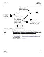


•
The regulated voltage should still be in band near the center of the band width.
•
The DVAR current on Transformer 1 should be lagging
•
The DVAR current on Transformer 2 should be leading
•
The DVAR current on Transformers 1 and 2 should have the same magnitude
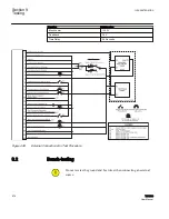
10. Verify that Transformer 1 is calling for a lower and Transformer 2 is calling for a
raise.
11. If both transformers are not calling for a tap change operation, then manually
increase the tap position difference between the transformers by raising Transformer
1, one tap and lowering Transformer 2 one tap until both controls are calling for the
correct operation.
This keeps the regulated voltage near the center of the bandcenter setting and
therefore any operations by the controls will be caused by the DVAR current.
12. Simultaneously place both transformers into Automatic operation and observe
where the transformers stop initiating tap changes.
The transformers should be on the same tap or one tap part, with the controls not
calling for any operations. If the high side is not connected then the tap positions
should be the same number of taps apart as noted above.
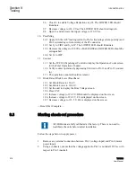
13. Place Transformer 1 and Transformer 2 in Manual.
14. Raise or Lower either Transformer 1 or Transformer 2 by one tap to generate some
DVAR current.
The transformer with the higher voltage (typically the higher tap) will have the
lagging DVAR current and the other transformer will have the same magnitude but
will indicate a leading DVAR current. If the load is not evenly distributed between
the transformers, then the voltage on the transformer with the larger load may
decrease and the control may call for a raise. The voltage on the transformer with the
smaller load may increase and its control may call for a lower.
15. Open the Tie Breaker between Transformer 1 and Transformer 2 and verify that the
controls are not calling for any tap change operations.
The load current does not have to be the same when the Tie Breaker opens and the
voltage may change based on the loading of the transformers.
16. Verify that the DVAR current is at or near zero.
17. If necessary, manually initiate tap change operations to bring the voltage back into
band.
18. Manually place the transformers to the same tap position (or the same difference as
noted above).
19. Close the Tie Breaker between Transformer 1 and Transformer 2 and verify that the
DVAR current in all transformers is at or near zero.
Assuming all the transformers are the same and the high side sources are all
connected together, only one high side source for the paralleled transformers. If the
high side is not connected together then may need to adjust the tap positions to get
zero DVAR current or the minimum value possible.
20. Manually Lower Transformer 1, one or two taps.
21. Manually Raise Transformer 2, one or two taps.
The regulated voltage should still be in band near the center of the band width.
Section 9
1VAC388793-MB A
Testing
586
TCC300
User Manual
Содержание TCC300
Страница 1: ...Digital Tapchanger Control TCC300 User Manual ...
Страница 2: ......
Страница 3: ...Document ID 1VAC388793 MB Issued 2016 08 10 Revision A Copyright 2016 ABB All rights reserved ...
Страница 22: ...Updating data file remotely 700 Section 16 Glossary 705 Table of contents 16 TCC300 User Manual ...
Страница 26: ...20 ...
Страница 34: ...28 ...
Страница 91: ...1VAC388793 MB A Section 3 Operation TCC300 85 User Manual ...
Страница 126: ...120 ...
Страница 176: ...Section 4 1VAC388793 MB A TCC600 170 TCC300 User Manual ...
Страница 260: ...254 ...
Страница 328: ...322 ...
Страница 494: ...488 ...
Страница 556: ...550 ...
Страница 580: ...574 ...
Страница 600: ...594 ...
Страница 700: ...694 ...
Страница 710: ...704 ...
Страница 712: ...706 ...
Страница 713: ...707 ...
Страница 714: ......
Страница 715: ......