


7.8.1
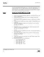
Step VAr bias method
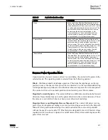
Table 66:
Step VAr Bias method settings
Setting
Description
Disable on Reverse Power
When selected, the control will disable VAr Bias
when Reverse Power is detected.
Forward Power Max 3 Phase Cap Bank Size
Adjustable from 4 to 12000 KVAr.
Reverse Power Max 3 Phase Cap Bank Size
Adjustable from 4 to 12000 KVAr.
Lead % Bank Size Pickup
Defines a Lower negative VAr limit in percentage of
the Max Cap Bank size below which the control will
increase the upper band edge by the amount defined
by VAr Bias Voltage Step.
Lag % Bank Size Pickup
Defines an Upper positive VAr limit in percentage of
the Max Cap Bank size above which the control will
decrease the lower band edge by the amount
defined by VAr Bias Voltage Step.
VAr Bias Voltage Step
Amount by which the control will increase or
decrease the Upper or Lower band edges when
there is a VAr Bias out of band situation.
Max VAr Bias Duration
Maximum allowable time in minutes the control will
bias the voltage edge.
When the control determines that the reactive power is lower or greater than the limits
defined by the Lead or Lag % pickup setting, the control will start an inverse VAr Bias
Pickup Trigger timer. After the inverse time expires, the control will either increase or
decrease the effective bandcenter by the amount defined by the VAr Bias Step Voltage
setting depending on the direction of the reactive power. At this moment VAr Bias
becomes active. The use of an inverse timer is to avoid jittering in the VAr Bias detection
and also to provide a faster response as the difference between the Upper or Lower VAr
Bias band edge and the measure VArs increase. For example, suppose the system is highly
inductive (positive VArs) the load voltage will tend to decrease, when VAr Bias is in
effect, the control will automatically reduce the lower band edge and thus the control will
be back in band, allowing the downstream cap controls to operate.
The longest allowable time delay before VAr Bias comes into effect is 10 seconds. The
inverse timer follows the following equation:
Time delay = 10 *(Upper or Lower VAr Limit)/IVAr measured.
Upper VAr limit is defined as Lag % Bank Size Pickup multiply by a third of Max Cap
Bank size.
Lower VAr limit is defined as Lead % Bank Size Pickup multiply by a third of Max Cap
Bank size.
Section 7
1VAC388793-MB A
Setpoints
540
TCC300
User Manual
Содержание TCC300
Страница 1: ...Digital Tapchanger Control TCC300 User Manual ...
Страница 2: ......
Страница 3: ...Document ID 1VAC388793 MB Issued 2016 08 10 Revision A Copyright 2016 ABB All rights reserved ...
Страница 22: ...Updating data file remotely 700 Section 16 Glossary 705 Table of contents 16 TCC300 User Manual ...
Страница 26: ...20 ...
Страница 34: ...28 ...
Страница 91: ...1VAC388793 MB A Section 3 Operation TCC300 85 User Manual ...
Страница 126: ...120 ...
Страница 176: ...Section 4 1VAC388793 MB A TCC600 170 TCC300 User Manual ...
Страница 260: ...254 ...
Страница 328: ...322 ...
Страница 494: ...488 ...
Страница 556: ...550 ...
Страница 580: ...574 ...
Страница 600: ...594 ...
Страница 700: ...694 ...
Страница 710: ...704 ...
Страница 712: ...706 ...
Страница 713: ...707 ...
Страница 714: ......
Страница 715: ......