


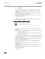


GUID-D6DD2EAF-5392-4BE6-BB3B-64BE90567BF6 V1 EN
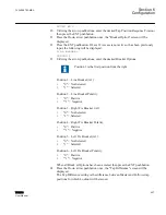
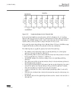
Figure 348:
Single Bus Breaker/Control Network Map
LB1 through LB8 are the Line Breakers and TB1-2 through TB7-8 are the Tie Breakers.
The user is required to enter the position of each control in the network.
The upstream control will be given Position 8 and consecutively decrement this number
as the user moves towards the downstream of this control. It is important to note that the
user should activate the Position 8 control last since this control is the Initiator, the one
responsible to start any timing signal/messages.
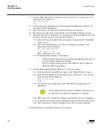
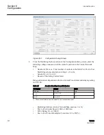
Ring bus
represents a Ring Bus with 8 transformers.
TCC300
T1
Position 1
i1
TCC300
T2
Position 2
i2
TCC300
T3
Position 3
i3
TCC300
T4
Position 4
i4
TCC300
T5
Position 5
i5
TCC300
T6
Position 6
i6
TCC300
T7
Position 7
i7
TCC300
T8
Position 8
i8
LB1
LB2
LB3
LB4
LB5
LB6
LB7
LB8
TB1-2
TB2-3
TB3-4
TB4-5
TB5-6
TB6-7
TB7-8
Ring Bus
High Side Bus
Low Side Bus
TB8-1
GUID-AFAE6202-2A2C-4B46-ABC8-B97C60D95344 V1 EN
Figure 349:
Ring Bus Breaker/Control Network Map
Section 6
1VAC388793-MB A
Configuration
432
TCC300
User Manual
Содержание TCC300
Страница 1: ...Digital Tapchanger Control TCC300 User Manual ...
Страница 2: ......
Страница 3: ...Document ID 1VAC388793 MB Issued 2016 08 10 Revision A Copyright 2016 ABB All rights reserved ...
Страница 22: ...Updating data file remotely 700 Section 16 Glossary 705 Table of contents 16 TCC300 User Manual ...
Страница 26: ...20 ...
Страница 34: ...28 ...
Страница 91: ...1VAC388793 MB A Section 3 Operation TCC300 85 User Manual ...
Страница 126: ...120 ...
Страница 176: ...Section 4 1VAC388793 MB A TCC600 170 TCC300 User Manual ...
Страница 260: ...254 ...
Страница 328: ...322 ...
Страница 494: ...488 ...
Страница 556: ...550 ...
Страница 580: ...574 ...
Страница 600: ...594 ...
Страница 700: ...694 ...
Страница 710: ...704 ...
Страница 712: ...706 ...
Страница 713: ...707 ...
Страница 714: ......
Страница 715: ......