


Item
Description
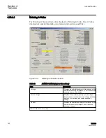
VAr Bias Effect
Indicates one of three conditions when enabled. If
the control has determined that the absolute reactive
power is >¾ of the Max Cap Bank Setting and the
inverse timer has timed out, then the control will
increase the effective bandcenter by 1 Volt
depending on the direction of the reactive power and
will either indicate "Bandcenter Raise" for negative
reactive power or "Bandcenter Lower" for positive
reactive power. If the absolute power is <¾ of the
Max Cap Bank Setting then the display will indicate
"None".
Whenever VAr Bias is in effect, the control will
display the "VAr Bias in effect" message on the
display and the appropriate Raise/Lower LED will
flash.
Power Direction
Indicates one of two power directions: Forward
(forward power condition) and Reverse (reverse
power condition).
Voltage Reduction VR Off
Indicates voltage reduction is not active, blocked
either by non‑sequential input, a reverse power
condition, or by communicated command. Steps 1,
2, and 3 indicate that voltage reduction is in effect for
the stated step value.
HMI Active Mode
Indicates (Yellow) that HMI menu at the control is
active.
Table 15:
ALARM STATUS
Item
Description
Comm Block
The control has had its automatic operation blocked
via communications and is now in manual operation
mode and the alarm output is on due to this condition.
Block Raise (Tap)
The tap position equals or exceeds the block raise
tap limit setting and the alarm output is on due to this
condition.
Block Lower (Tap)
The tap position equals or exceeds the block lower
tap limit setting and the alarm output is on due to this
condition.
Block Raise (Voltage)
The tap position equals or exceeds the block raise
voltage limit setting and the alarm output is on due to
this condition.
Block Lower (Voltage)
The tap position equals or exceeds the block lower
voltage limit setting and the alarm output is on due to
this condition.
DVar2 Load Current Limit
DVar2 Load Current is exceeding the respective
maximum current limit setting and the alarm output is
on due to this condition.
Motor Seal-In Failure
Indicates that motor current has not been detected
for a period 15 seconds after a Raise or Lower
command has been executed. This event must occur
two consecutive times for this alarm to occur.
Table continues on next page
Section 4
1VAC388793-MB A
TCC600
156
TCC300
User Manual
Содержание TCC300
Страница 1: ...Digital Tapchanger Control TCC300 User Manual ...
Страница 2: ......
Страница 3: ...Document ID 1VAC388793 MB Issued 2016 08 10 Revision A Copyright 2016 ABB All rights reserved ...
Страница 22: ...Updating data file remotely 700 Section 16 Glossary 705 Table of contents 16 TCC300 User Manual ...
Страница 26: ...20 ...
Страница 34: ...28 ...
Страница 91: ...1VAC388793 MB A Section 3 Operation TCC300 85 User Manual ...
Страница 126: ...120 ...
Страница 176: ...Section 4 1VAC388793 MB A TCC600 170 TCC300 User Manual ...
Страница 260: ...254 ...
Страница 328: ...322 ...
Страница 494: ...488 ...
Страница 556: ...550 ...
Страница 580: ...574 ...
Страница 600: ...594 ...
Страница 700: ...694 ...
Страница 710: ...704 ...
Страница 712: ...706 ...
Страница 713: ...707 ...
Страница 714: ......
Страница 715: ......