


7.8.2
Linear VAr bias method
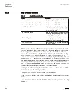
Table 67:
Linear VAr Bias method settings
Setting
Description
Disable on Reverse Power
When selected, the control will disable VAr Bias
when Reverse Power is detected.
Current Multiplier Base Value
Adjustable from 0 to 32600.
No Voltage Reduction – Linear Voltage Bias (-X)
The Linear Voltage Bias (-X) setting defines the
amount of voltage bias to be applied to the
Bandcenter when at 1 PU reactive current loading.
Adjustable from -72 to 0 Volts at 200 mA Reactive
Load.
No Voltage Reduction – Linear Voltage Bias (-X)
Limit
The Linear Voltage Bias (-X) Limit, limits the total
voltage bias that can affect the control
Bandcenter.Adjustable from -5.0 to 0.0 Volts.
During Voltage Reduction – Linear Voltage Bias (+X) The Linear Voltage Bias (+X) setting defines the
amount of voltage bias to be applied to the
Bandcenter when at 1 PU reactive current loading.
Adjustable from 0 to 72 Volts at 200 mA Reactive
Load.
During Voltage Reduction – Linear Voltage Bias (+X)
Limit
The Linear Voltage Bias (+X) Limit, limits the total
voltage bias that can affect the control Bandcenter.
Adjustable from 0.0 to 5.0 Volts.
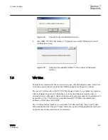
The Linear VAr Bias feature allows a Regulator or LTC Control to coordinate operations
with Capacitor Banks downstream of the Regulator or LTC. The Linear VAr Bias feature
utilizes the reactive load current measurement capability of the TCC300 to adjust the
Bandcenter of the control in order to bias downstream capacitors to operate to maintain a
flat voltage profile.
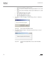
When enabled the regulator will bias the Bandcenter of the control based on the amount
of measured reactive load current. Additionally, if LDC settings are non-zero values in the
control, they are disabled while Linear VAr Bias is selected. A Linear Voltage Bias (-X)
Setting is created which defines the amount of voltage bias to be applied to the Bandcenter
when at 1 PU reactive current loading. A Linear Voltage Bias (-X) Limit is created which
limits the total voltage bias that can affect the control Bandcenter.
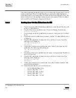
A Max Bias Duration setting is also included that limits the maximum allowable time in
minutes that the control will bias the voltage edge as long as no Voltage Reduction (VR)
is in effect.
When a VR is in effect, the Linear Voltage Bias (+X) and a Linear Voltage Bias (+X)
Limit are used instead of the (-X) Limits to bias the control Bandcenter. In effect, when
enabled the user sets the Linear VAr Bias setting values at which bandcenter/bandwidth
is shifted to influence downstream Capacitor Control(s) into operation.
1VAC388793-MB A
Section 7
Setpoints
TCC300
545
User Manual
Содержание TCC300
Страница 1: ...Digital Tapchanger Control TCC300 User Manual ...
Страница 2: ......
Страница 3: ...Document ID 1VAC388793 MB Issued 2016 08 10 Revision A Copyright 2016 ABB All rights reserved ...
Страница 22: ...Updating data file remotely 700 Section 16 Glossary 705 Table of contents 16 TCC300 User Manual ...
Страница 26: ...20 ...
Страница 34: ...28 ...
Страница 91: ...1VAC388793 MB A Section 3 Operation TCC300 85 User Manual ...
Страница 126: ...120 ...
Страница 176: ...Section 4 1VAC388793 MB A TCC600 170 TCC300 User Manual ...
Страница 260: ...254 ...
Страница 328: ...322 ...
Страница 494: ...488 ...
Страница 556: ...550 ...
Страница 580: ...574 ...
Страница 600: ...594 ...
Страница 700: ...694 ...
Страница 710: ...704 ...
Страница 712: ...706 ...
Страница 713: ...707 ...
Страница 714: ......
Страница 715: ......