


GUI Reference
R&S
®
ZNA
270
User Manual 1178.6462.02 ─ 12
●
"Add CW Mode"
Activates a new channel for the spectrum measurement. The "CW Frequency" plus
half the "Tone Distance" defines the center of the diagram.
●
"Spectrum = Marker"
This button is only available if the analyzer is equipped with software option
R&S
ZNA-K1; see
on page 386. If there is no marker in the
active intermodulation trace, the center frequency of the related channel is used.
●
"Max IM Order"
Defines the width of the spectrum measurement.
Remote command:
[SENSe<Ch>:]FREQuency[:CW]
[SENSe<Ch>:]FREQuency:IMODulation:MSPectrum
[SENSe<Ch>:]FREQuency:IMODulation:SPECtrum:MORDer
[SENSe<Ch>:]FREQuency:IMODulation:SPECtrum[:STATe]
6.2.6.2
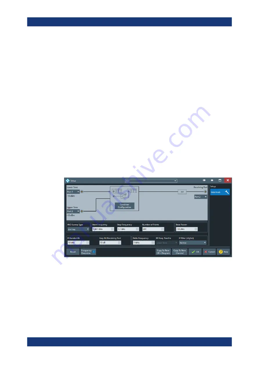
Intermodulation Setup Dialog
The intermodulation setup dialog is an instance of the
allows you to set up one or more channels for intermodulation measurements on a
non-frequency converting DUT.
Access:
Trace – [Meas] ("Non-Frequency Converting") > "Intermodulation" > "Inter-
mod."
Figure 6-2: Intermodulation Setup Dialog (non-frequency converting DUT)
Port and Signal Path Setup
The graphical part of the dialog allows you to define the related ports and the signal
path.
Lower Tone
Selects an analyzer port as a source of the lower tone signal.
Meas Softtool


