background image

52

Type

Name

Code

Functions

Refer

C

ha

ra

ct

er S

et

tin

g

Character entry (by ASCII code)

MCS

Sets the characters of the character objects (reference 
list type) by the ASCII code. Alpha-numeric characters 
and symbols are available.

(P.69)

Character entry (by ASCII and 
Shift-JIS code)

STR

Sets the characters of the character objects (reference 
list type). Characters including alpha-numeric, 
functional characters and Japanese characters are 
available.

(P.70)

Character entry per trigger

SIN

When “Characters specified by SIN command” is set 
for character objects or barcode/2D code objects, 
input characters with this command. Send this 
command per each marking.

(P.72)

Character object settings

STC

Sets the position and size of the character object 
(reference list type) and conditions including text 
characteristics.

(P.74)

Character object settings 
(shortened)

SPC

Sets only X-/Y-position and laser power correction in 
the character object settings.

(P.78)

Fu

nc

tio

na

l c

ha

ra

ct

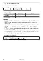
er

s

Counter settings

CNT

Configures the “counter” function used to mark 
consecutive numbers.

(P.79)

Counter reset

CTR

Resets the current value to the starting value.

(P.80)

Expiry date/time settings

LMT

Configures the “expiry” function used to mark the date 
with a specified period added or subtracted to/from 
the current date.

(P.81)

Lot settings

LTC

Configures the “Lot” function used to change 
characters depending on the date/time and counter 
values.

(P.82)

Lot character

LTS

Sets the characters used with the “Lot” function to 
change characters depending on the date/time and 
counter values.

(P.83)

Registered character settings

RKC

Sets the input format of the “Registered characters” 
function used to switch characters by I/O input.

(P.85)

Registered character strings

RKS

Sets the character string used with the “Registered 
characters” function that switches characters by I/O 
input.

(P.86)

B

ar

 C

ode

/2

D

 C

ode

Bar code/2D code characters (by 
ASCII code)

BCS

Sets the characters to encode of the bar code/2D 
code objects by the ASCII code. Alpha-numeric 
characters and symbols are available.

(P.87)

Bar code/2D code characters (by 
ASCII and Shift-JIS code)

BRS

Sets the characters to encode of the bar code/2D 
code objects. Characters including control codes 
(specified with 2-byte alternative codes), alpha-
numeric, functional characters, and Japanese 
characters are available.

(P.89)

Bar code/2D code object settings

BRF

Sets the conditions such as the position and size of 
the bar code/2D code as well as code characteristics.

(P.91)

Human readable text settings

BRV

Sets the character conditions to mark the character 
strings of bar code/2D code as the human readable 
text.

(P.100)

Module filling of 2D codes

BRP

Sets the laser settings and filling details with a font by 
each element of the 2D code.

(P.103)

ME-LP-GS-SR-COMP-3

Summary of Contents for LP-GS Series

Page 1: ...LP GS series LP RC series LP RF series LP RV series 2019 4 panasonic net id pidsx global ME LP GS SR COMP 3 Laser Marker Serial Communication Command Guide LP 400 V compatible mode...

Page 2: ...lity for any results arising out of operations regardless of the above clauses Disclaimer The applications described in this document are all intended for examples only The purchase of our products de...

Page 3: ...ions to be observed This symbol is used to alert users to a specific operating procedure that must not be performed This symbols is used to alert users to a specific operating procedure that must be f...

Page 4: ...er radiation for the maintenance door of the protective enclosure After power supply of laser marker is turned off laser safety manager must remove the key and keep it Be sure to connect the head and...

Page 5: ...protect operators from exposure ignition toxic effect excess or lack of oxygen To carry this product wear the non slip gloves and safety shoes Hold the product with both hands Do not hold the cables o...

Page 6: ...or specifications vary by models the target models are specified in the text In the text multiple models may be described collectively as shown in the table below Please remind that the illustration...

Page 7: ...e screen operations to set marking contents Mainly the users that operate this laser marker for actual marking procedure shall be required for reading this manual Serial Communication Command Guide Th...

Page 8: ...Communication settings 23 1 4 3 Connecting to external control devices and its setting sample 24 1 5 Checking the communication commands 25 2 Communication Control Basics 26 2 1 Communication Data Typ...

Page 9: ...70 3 5 3 Character entry per trigger SIN 72 3 5 4 Character object settings STC 74 3 5 5 Character object settings shortened SPC 78 3 6 Functional Character Commands 79 3 6 1 Counter settings CNT 79...

Page 10: ...11 3 Line speed LSP 125 3 11 4 Workpiece spacing INT 126 3 12 Laser Setting Commands 127 3 12 1 Laser power LPW 127 3 12 2 Scan speed SSP 128 3 12 3 Laser frequency pulse cycle MPL 129 3 12 4 Laser fi...

Page 11: ...1 Preparation of Command Control ME LP GS SR COMP 3...

Page 12: ...ce Guide External control remote mode by serial communication commands RS 232C Ethernet To control the laser marker by communication commands from external devices such as PLC use RS 232C or Ethernet...

Page 13: ...ds I O control OPEN shutter Remote mode ON Select file Confirm READY OUT is ON Trigger Input ON Laser pumping ON Control by using I O or communication commands It is available to the external control...

Page 14: ...I O or communication commands As the default I O control is selected to all settings Laser pumping control Shutter control Guide laser control 1 1 Available with LP GS051 L type LP 350S LP RF series a...

Page 15: ...work piece is in position for lasing Terminal assignment X11 LP GS series only Select the behavior of the input signal X11 on I O terminal from LASER STOP 1 IN or LASER STOP 2 IN Initial setting LASE...

Page 16: ...standard communication format and not applied to LP 400 LP V compatible format For the details of the standard command format refer to the Serial Communication Command Guide For the command format of...

Page 17: ...Use the remote mode switch button of Laser Marker NAVI smart for releasing and resetting the remote mode If you want to start up the laser marker in the remote mode you need to configure the settings...

Page 18: ...To use the RS 232C port select the RS 232C usage from communication command control or code reader linkage function in the system settings screen in advance w Ethernet port For the connection details...

Page 19: ...Connector specifications Model Manufacturer name On the laser marker side D sub 9 pin female Screw type No 4 40UNC inch screw female User side D sub 9 pin male Screw type No 4 40UNC inch screw male R...

Page 20: ...other than RxD RD TxD SD or GND on the external control device side depending on the specifications of the external control device Read the instruction manual of the external control device and connec...

Page 21: ...None Check sum OFF ON initial setting OFF End code CR CR LF initial setting CR Start code Setting request data Readout request data Response data for readout STX Positive response code ACK Negative re...

Page 22: ...ge checker On the laser marker controller side LP GS series Rear of Controller LP RC LP RF LP RV series Rear of Controller RJ 45 8 pole connector AUTO MDIX compatible Orange LED Green LED Light up col...

Page 23: ...r through the Ethernet should be performed in a secure network settings Even the IP Address and Subnet Mask values are within the configurable range they may not be available depending on the combinat...

Page 24: ...controller PC etc Laser marker controller Several units connected Example of communication system settings Set a separate IP address not to overlap between the laser marker and PC on the network PC La...

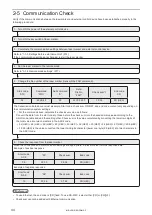
Page 25: ...NAVI smart and the laser marker online 2 Click the screen selection menu and select Maintenance 3 Select Command history tab Up to 100 command messages received or sent by the laser marker are shown...

Page 26: ...2 Communication Control Basics ME LP GS SR COMP 3...

Page 27: ...laser marker operations Readout request Request data to read out the status or setting data of the laser marker 2 1 2 Response data The response data is sent from the laser marker to the external dev...

Page 28: ...ic message once again Communication sequence of setting readout request data When the requested data was received normally from the external device the laser marker transmits positive response to the...

Page 29: ...P 63 When the response permission of the marking end verification MST command is set Laser marker Positive response ACK00 Positive response ACK00 Marking trigger command MRKS1 Marking trigger command...

Page 30: ...g in progress trigger ready OFF Status readout response STSA02110 Non marking state trigger ready ON Send the next request command after confirming the marking completed with STS response Check the la...

Page 31: ...f three characters 3 byte representing the control contents For command types and description refer to 3 1 Command List P 51 Sub command 1 One byte alphabetic character representing the communication...

Page 32: ...from the external device Setting request data format Request data to modify or create the laser marker data or to control the laser marker operations The start code is STX 02 HEX The sub command is S...

Page 33: ...ontent for the readout request data sub command R The start code is STX 02 HEX The sub command is A Start code STX Command Sub command A Variable length data or fixed length data Check sum End code 1...

Page 34: ...th LP 400 V compatible command mode 05 Incorrect check sum 06 Incorrect data length 07 Unacceptable command for the I O terminal control settings 08 Incorrect sub command 09 Invalid variable length or...

Page 35: ...r pumping is not ready LP RC series only SHT command for opening shutter request is sent when laser pumping is off 19 Unacceptable command with current settings of trigger mode Unacceptable command wi...

Page 36: ...Code Table P 163 You cannot shorten the numeric data length It is not allowed to omit and 0 in upper digit For numeric data including a decimal point the number of digits of the integer part and the d...

Page 37: ...nce list by ASCII and Shift JIS code The ASCII code and Shift JIS code can be mixed In the response data for readout all characters except the functional characters are readout in Shift JIS code To in...

Page 38: ...o Bar code 2D code object depending on the code type the acceptable character type is restricted to either one byte or two byte character In this case the input character is converted automatically to...

Page 39: ...UL to US DEL ASCII code HEX 00 to 1F 7F Alternative code HEX F050 to F06F F071 If you want to set FNC1 with BRS command use the 2 byte alternative code F072 HEX for FNC1 Command Control code Alternati...

Page 40: ...not set Z 1 to 9 A to Z Represents the counter numbering system Input the numbers 1 value Z is omitted for the decimal number At LP 400 V compatible command mode G to J are converted to 4 to 7 when th...

Page 41: ...e LP RF LP RV series only When the character strings set with the functional character are read out by STR command or BRS command the data with the functional character set to start with described ear...

Page 42: ...nd reception permission MKM command before transmitting a command marking trigger ready is set to OFF and commands get acceptable Set reception mode OFF for command reception permission MKM command to...

Page 43: ...warning occurrence The laser marker accepts only the following commands while an alarm or warning occurs Alarm Status checking STS Warning Status checking STS Shutter open close SHT Shutter close requ...

Page 44: ...converting the lower two digits of the total value into two characters in the ASCII code 02 HEX 46 HEX 4E HEX 4F HEX 53 HEX 32 HEX 30 HEX 34 HEX 37 HEX 205 HEX 30 35 HEX is the value converted the lo...

Page 45: ...ng the laser pumping on request to completion of laser pumping the following time will be required LP GS series about 8 to 15 seconds LP RC series about 10 seconds LP RF series about 7 seconds LP RV s...

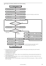
Page 46: ...ommand reception permission OFF Marking trigger ready ON Yes Yes No Finish operation No Remote mode ON Create marking data and start marking 1 From sending the laser pumping on request to completion o...

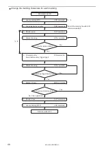
Page 47: ...d Transmit the characters you want to mark Marking trigger ready ON Yes Yes No Finish operation No Mark the same characters No 1 From sending the laser pumping on request to completion of laser pumpin...

Page 48: ...SHT command 4 Status checking STS command 5 Character entry SIN command Send before every trigger input 6 Status checking STS command 7 Marking trigger MRK command 8 Shutter close SHT command 9 Laser...

Page 49: ...time of around 200ms to max 1 second from sending shutter open close command for the actual shutter open close operation time Besides with LP RC series for the first operation of opening shutter afte...

Page 50: ...3 Data Format for Each Command ME LP GS SR COMP 3...

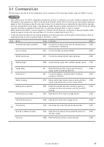
Page 51: ...e Code Functions Refer Operation Control Command reception permission MKM Controls the reception permission for the settings by communication commands P 56 Laser pumping LSR Controls the laser pumping...

Page 52: ...81 Lot settings LTC Configures the Lot function used to change characters depending on the date time and counter values P 82 Lot character LTS Sets the characters used with the Lot function to change...

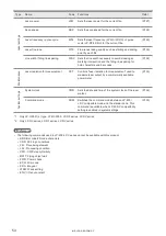
Page 53: ...king position for the entire marking data in the file P 114 External offset values OFS Sets offset value of marking position used for External Offset Function with I O input P 115 Step repeat settings...

Page 54: ...ation for measurement used to measure laser output by a commercially available power meter P 133 System settings System clock YMD Sets the date and time of the system clock of the laser marker P 134 C...

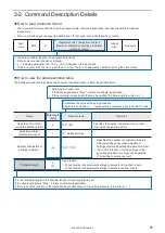
Page 55: ...r the number from which the deletion starts Adjustment object Delete command 1 0 Delete settings Number of adjustment settings to delete 3 001 100 Specifies the number of conditions to delete before d...

Page 56: ...ommand reception permission ON 1 Command reception permission OFF Setting command reception permission ON turns OFF the marking trigger ready to start receiving commands Setting command reception perm...

Page 57: ...est to completion of laser pumping the following time will be required LP GS series about 8 to 15 seconds LP RC series about 10 seconds LP RF series about 7 seconds LP RV series about 1 second For LP...

Page 58: ...om sending shutter open close command for the actual shutter open close operation time With LP RC series for the first operation of opening shutter after the laser pumping on it takes around 300ms to...

Page 59: ...shing the running marking and subsequent triggers are canceled Closing the shutter Sending MKM command with command reception permission ON Changing the file Changing the marking characters by code re...

Page 60: ...ected file When you use several files set the trigger delay for each file When in the selected file the link control with an image checker is set the link control starts after the trigger delay time T...

Page 61: ...n start the guide laser radiation only with the internal shutter closed The guide laser stops automatically after about one minute has passed from the startup When on the fly marking is set for LP RC...

Page 62: ...reception permission MKM command status Use this for determination of whether various commands can be transmitted For details refer to 2 4 Command Reception Condition P 42 When the shutter is closed...

Page 63: ...the setting request data and A for the response data for readout Readout request data Start code MST R Check sum End code Data description Name Data length byte Data contents Remarks Response setting...

Page 64: ...r error codes details The automatic response data of the error code will not be transmitted in case of errors occurred when the marking trigger processing is not in progress When on the fly marking wi...

Page 65: ...e Data description Name Data length byte Data contents Remarks File number 4 0000 9999 Response data for readout returns the file number currently selected Total data length 4 The data length is fixed...

Page 66: ...cifies a case sensitive alphabetical file name If the file name contains both the ASCII code one byte characters and Shift JIS code two byte characters specify them exactly as they are in the ASCII co...

Page 67: ...in the laser marker without overwriting operation Current counter value of counter settings CNT Counter reset CTR Motion settings TRG Encoder resolution ENC System clock YMD 3 4 4 Save file to differe...

Page 68: ...characters single byte characters Use the Shift JIS code to specify two byte characters double byte characters Total data length Max 20 Variable length Refer to 2 3 5 Character data input method P 37...

Page 69: ...read out in shift JIS code If the marking character string contains any functional characters or 2 byte characters the maximum readout data can be 60 byte Total data length Max 32 Variable length Set...

Page 70: ...2 byte Check sum End code Data description Name Data length byte Data contents Remarks String No 2 01 50 string No 1 to 50 for current file 51 60 string No 101 to 110 for all files Select the string N...

Page 71: ...ut The characters to mark as the functional characters such as the counter or date and time values are not read out With LP 400 V compatible command mode you cannot readout the character strings with...

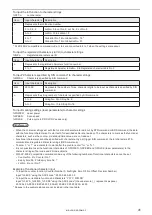
Page 72: ...tal data length Max 200 Variable length Refer to 2 3 5 Character data input method P 37 for details on the character input method and character types with input restrictions To use this SIN command se...

Page 73: ...AIT OUT No 38 to know the timing of SIN command input SIN command can be accepted only when the shutter is open The shutter status can be confirmed by using SHUTTER OPEN OUT signal of I O When command...

Page 74: ...byte Check sum End code Data description 1 When the character arrangement is straight line Name Name in LP 400 V Data length byte Data contents Remarks Object No Character condition No 2 01 60 Object...

Page 75: ...th 7 Model Setting range mm LP GS051 L 000 000 055 000 LP GS052 000 000 030 000 LP RC350S 000 000 085 000 LP RF200P LP RV200P 000 000 090 000 Specifies a character spacing for fixed spacing proportion...

Page 76: ...nal of arc cannot be set and readout Horizontal and vertical alignment 1 0 Left and first baseline 1 Center and first baseline 2 Right and first baseline Specifies which point in the character strings...

Page 77: ...data length 80 or 83 The data length is fixed LP GS LP RC series 80 byte LP RF LP RV series 83 byte Only for LP RF series and LP RV series Example of command settings Condition When the character arr...

Page 78: ...e response data for readout Readout request data Start code SPC R Object No 2 byte Check sum End code Data description Name Name in LP 400 V Data length byte Data contents Remarks Object No Character...

Page 79: ...The counter current value change is saved to the laser marker without overwriting operation Starting value 6 If the starting value is larger than the end one it works as a subtraction counter End val...

Page 80: ...e current value to the starting value Setting request data Start code CTR S Counter 0 Counter 1 Counter 2 Counter 3 Global counter 16 Global counter 17 Global counter 18 Global counter 19 8 byte Check...

Page 81: ...99 It is the period added or subtracted to from the current date and time Expiry time unit 1 0 Year 1 Month 2 Date 3 Hour 4 Minute It is the unit of the period added or subtracted to from the current...

Page 82: ...r 16 to 19 Specifies which function you are referencing the current date time expiry date or counter to switch lot characters Lot unit 1 0 Year or counter 1 Month 2 Day 3 Year and month 4 Month and da...

Page 83: ...data Start code LTS R Lot No Period No 3 byte Check sum End code Data description Name Data length byte Data contents Remarks Lot No 1 0 3 Lot 0 to 3 4 7 Global lot 16 to 19 You cannot select the lot...

Page 84: ...haracters Input Method ASCII code or Shift JIS code can be mixed Use the ASCII code to specify one byte characters single byte characters Use the Shift JIS code to specify two byte characters double b...

Page 85: ...ength byte Data contents Remarks I O input format 1 1 4 bit x 4 2 8 bit x 2 It is the assignation method of the data number for I O terminal Total data length 1 The data length is fixed Example of com...

Page 86: ...55 D8 to 15 256 511 Data number which sets characters The setting range varies depending on the I O input format Registered characters Min 0 Max 18 The number of input characters allowed Max 9 charact...

Page 87: ...r The linefeed is not included in the code data If the code data length is more than 30 byte set the character in the several string No They are connected together in numerical order without linefeed...

Page 88: ...it is shown as FNC1 For the response data for readout it is readout as GS To set other control codes than GS or FNC1 use BRS command If the readout data includes characters that cannot be expressed i...

Page 89: ...The linefeed is not included in the code data If the code data length is more than 60 byte set the character in the several string No They are connected together in numerical order without linefeed to...

Page 90: ...character strings P 39 For response data for readout all characters except the functional characters are readout in 2 byte characters Shift JIS code regardless the settings When the character strings...

Page 91: ...tting request data and A for the response data for readout Readout request data Start code BRF R Object No 1 byte or 2 byte 2D side of composite code Check sum End code Data description 1 When the cod...

Page 92: ...000 999 The correction ratio is calculated using the value set at the laser settings as 100 Scan speed correction 3 001 999 Pulse cycle correction 3 001 999 Total data length 54 or 57 The data length...

Page 93: ...tion 8 999 999 999 999 mm It is the center coordinate of the code Y position 8 Rotation angle 7 180 00 180 00 The rotation center is the center of the code symbol Quiet narrow ratio 4 00 0 20 0 Ratio...

Page 94: ...ition 8 999 999 999 999 mm It is the center coordinate of the code Y position 8 Rotation angle 7 180 00 180 00 The rotation center is the center of the code symbol Module height vertical 5 0 001 9 999...

Page 95: ...e square Symbol size horizontal 2 X position 8 999 999 999 999 mm It is the center coordinate of the code Y position 8 Rotation angle 7 180 00 180 00 The rotation center is the center of the code symb...

Page 96: ...00 050 030 000 LP RC350S 000 050 085 000 LP RF200P LP RV200P 000 050 090 000 In Laser Marker NAVI smart this setting is converted to the ratio of the code height to module width and displayed as Bar c...

Page 97: ...setting is converted to the height ratio of the lower side to module width and displayed as Lower barcode height to module width ratio Separator height to module width ratio 4 00 0 10 0 Specifies the...

Page 98: ...0 12 rows 00 Auto sets the minimum value depending on the code data settings GS1 DataBar Limited CC A 00 Auto minimize setting 04 08 rows Number of columns for 2D side 2 00 Auto Separator height to mo...

Page 99: ...e vertical 24 Symbol size horizontal 24 X position 15 Y position 20 Rotation angle 0 Module height 1 Module width 1 Setting Transmission data STX BRF S 102002424 015 000 020 000 000 00 1 0001 000 CR R...

Page 100: ...length byte Data contents Remarks Object No Bar code No 1 0 7 Object No 1100 to 1107 Positional offset target 1 1 Bar code 2D code 1D side of the composite codes 2 2D side of the composite codes Selec...

Page 101: ...49 The data length is fixed LP GS LP RC series when linefeed is enabled 54 byte LP GS LP RC series when linefeed is disabled 47 byte or 46 byte LP RF LP RV series when linefeed is enabled 57 byte LP...

Page 102: ...dout Transmission data STX BRV R 1 CR Response data STX BRV A 11 010 000 005 500003 000003 000003 000 21002001001003 500 CR Condition When the linefeed is disabled Object No 1 Positional offset target...

Page 103: ...acter code Laser power correction Scan speed correction Pulse cycle correction LP GS LP RC 12 byte LP RF LP RV 15 byte Check sum End code Sub command is S for the setting request data and A for the re...

Page 104: ...length 12 or 15 The data length is fixed LP GS LP RC series 12 byte LP RF LP RV series 15 byte Only for LP RF series and LP RV series Example of command settings Condition Object No 1 Code element 2...

Page 105: ...o byte characters double byte characters You cannot delete a graphic file cannot specify it with 0 byte Total data length Max 256 Variable length Files configurable with this command are the graphic f...

Page 106: ...ut request data Start code CDC R Object No 2 byte Check sum End code Data description Name Name in LP 400 V Data length byte Data contents Remarks Object No Logo No 2 00 15 Object No 1200 to 1215 Syst...

Page 107: ...n 15 Y position 20 Rotation angle 120 Laser power correction 50 Scan speed correction 100 Setting Transmission data STX CDC S 0100200 0000200 000 015 000 020 000 120 00050100 CR Readout Transmission d...

Page 108: ...0 to 1415 Point No First No for setting 3 000 049 Max 50 points can be set in one object no Specifies the point no to be set When setting two or more points this no indicates the first no to be set Ra...

Page 109: ...code PRD S Object No Point No Radiation time Laser power correction 15 byte Check sum End code Data description Name Name in LP 400 V Data length byte Data content Remarks Object No Point radiation No...

Page 110: ...oints this number is the start point number to delete Specify the smaller no to the first point no than the last point no Last point No to delete 3 000 049 Deletes all points from the specified first...

Page 111: ...pecified point no these items are not included in the response data for readout The correction ratio of laser power is calculated using the value set at the laser settings as 100 Laser power correctio...

Page 112: ...99 999 999 mm Moves the all points set in the selected object no from currently set position Y offset 8 Laser power correction 3 000 999 The correction ratio is calculated using the value of laser pow...

Page 113: ...adout request data Start code ALC R Check sum End code Data description Name Name in LP 400 V Data length byte Data contents Remarks X movement 8 999 999 999 999 mm Moves the coordinate of the all mar...

Page 114: ...etting request data and A for the response data for readout Readout request data Start code OFC R Check sum End code Data description Name Data length byte Data contents Remarks Input method 1 0 OFF 1...

Page 115: ...arking data in the file The rotation center is the center of the marking field Y movement 8 Rotation movement 7 180 00 180 00 Total data length 26 Fixed length This command can be used when the input...

Page 116: ...23 byte or 1 byte Check sum End code Sub command is S for the setting request data and A for the response data for readout Readout request data Start code SRC R Check sum End code Data description Nam...

Page 117: ...sition of the counting in the step repeat When Count individually is enabled With the count direction Horizontal Setting Count Mark OFF Counter start 10 ON Top left 12 ON Top right 20 OFF Top left 22...

Page 118: ...r power correction 35 byte or 25 byte Check sum End code Sub command is S for the setting request data and A for the response data for readout Data description Name Data length byte Data contents Rema...

Page 119: ...3 X movement 0 1 Y movement 0 2 Rotation movement 0 Laser power correction 0 Setting Transmission data STX SRA S 001002003 000 100 000 200 or 001002003 000 100 000 200 000 00 00 CR Readout Transmissio...

Page 120: ...te after executing Step repeat When the rotation movement is omitted 000 00 is set Y movement 8 Rotation movement 7 180 00 180 00 Laser power correction 3 50 50 Corrects the laser power of the marking...

Page 121: ...the mark OFF is set to two or more data set the next row and column in series These settings are set in the subsequent adjustment No Max 100 pairs of row and column can be set Target row 3 Target colu...

Page 122: ...mitted 6 byte When Number of adjustment settings to delete is omitted 3 byte When only one adjustment No is deleted this item can be omitted If the sum of the adjustment number from which the deletion...

Page 123: ...command mode 2 sensors input cannot be set and readout Trigger mode 1 0 Single trigger 1 Marking at regular intervals Single trigger corresponds to trigger marking of LP 400 LP V series With LP 400 V...

Page 124: ...r resolution 6 byte Check sum End code Sub command is S for the setting request data and A for the response data for readout Readout request data Start code ENC R Check sum End code Data description N...

Page 125: ...request data and A for the response data for readout Readout request data Start code LSP R Check sum End code Data description Name Data length byte Data contents Remarks Line speed 7 000 060 240 000...

Page 126: ...is S for the setting request data and A for the response data for readout Readout request data Start code INT R Check sum End code Data description Name Data length byte Data contents Remarks Workpiec...

Page 127: ...nd Laser power 5 byte Check sum End code Sub command is S for the setting request data and A for the response data for readout Readout request data Start code LPW R Check sum End code Data description...

Page 128: ...m End code Sub command is S for the setting request data and A for the response data for readout Readout request data Start code SSP R Check sum End code Data description Name Data length byte Data co...

Page 129: ...code Sub command is S for the setting request data and A for the response data for readout Readout request data Start code MPL R Check sum End code Data description Name Data length byte Data content...

Page 130: ...000 100 With a larger value lasing time becomes longer Jump and system reserved values can be omitted If the jump is omitted omit the system reserved values too If the jump is omitted the value set l...

Page 131: ...e 1 Jump 0 System reserved value 0 00 System reserved value 0 00 Setting Transmission data STX WTC S 005 01001000002001 000000 000 00 or 005 01001000002001 00000 or 005 01001000002001 00 CR Readout Tr...

Page 132: ...End code Data description Name Data length byte Data contents Remarks Line width 5 0 010 2 000 mm It is the segment width for the purpose of calculation Applies to the value of the width for creating...

Page 133: ...laser radiation for measurement Even if you have set the different settings for the laser radiation for measurement by using Laser Marker NAVI smart the radiation settings are overwritten with the la...

Page 134: ...e data for readout Readout request data Start code YMD R Check sum End code Data description Name Data length byte Data contents Remarks Year 4 1980 2099 Year Month 2 01 12 Month Date 2 01 31 Day Hour...

Page 135: ...r Marker NAVI smart When LP 400 V compatibility is enabled in system settings of Laser Marker NAVI smart the command mode is always LP 400 V command mode at the time of starting the remote control mod...

Page 136: ...136 MEMO ME LP GS SR COMP 3...

Page 137: ...Troubleshooting ME LP GS SR COMP 3...

Page 138: ...UT COM 1 For LP RC LP RF LP RV series REMOTE INTERLOCK IN X20 OUT COM 1 Check the connection of each terminal on the I O terminal block If the safety equipment such as door and switch is in released s...

Page 139: ...mmunication settings in the system settings Then restart the laser marker Ethernet is not listed as an available laser marker search condition In the laser marker selection screen select the Including...

Page 140: ...ing correction factor Decrease scan speed including correction factor Laser type wavelength output power etc is not appropriate for material of the work piece Materials can be marked differ depending...

Page 141: ...t of the actual target work piece The LP GSxxx L type is excluded Set the Z position according to the work piece height Marking surface of work piece is inclined Make adjustment so that bottom surface...

Page 142: ...ent air cylinder and forklift etc Marking is disturbed at irregular intervals Start and or stop timing of feeder does not match with marking operation Disturbed at the beginning of marking Marking tri...

Page 143: ...Use Original 2 or Original 5 font for the small size characters Adjust the laser power or scan speed Marking is dotted For LP GS series Setting of laser frequency and scan speed is inadequate Decreas...

Page 144: ...of the moving direction is wrong Match feed direction with laser marker operation Check the setting direction of the laser head of the system settings screen Speed changes at conveyor junction If con...

Page 145: ...racter spacing is too wide Increase the setting When the character spacing is too narrow Decrease the setting In some cases it may reduce the influence of the ups and downs of the line speed to decrea...

Page 146: ...able is incorrect Check the applicable cable type and connecting conditions described in Setup Maintenance Guide for proper wiring For RS 232C connection confirm the wiring of the external device incl...

Page 147: ...the actual control method are consistent If the shutter open close method is changed in the system settings screen restart the laser marker File switching is not complete If the file number is change...

Page 148: ...trigger MRK Character entry per trigger SIN Marking position and laser power adjustment per trigger SEO Runtime data RTD Alarm or Warning occurred All commands except the following commands cannot be...

Page 149: ...order of X Y and theta The results of the code or character checking is NG Testing conditions of image checker are inadequate Set appropriate testing conditions of the image checker according to marke...

Page 150: ...uming marking ERROR CODE Description Measures 1 E001 E038 E045 E094 E101 E138 E145 E194 E202 E208 E214 E223 E224 E230 E245 E248 E300 E380 An error has occurred to the internal system of the laser mark...

Page 151: ...in the air intake and exhaust port and clean the air cooling part such as fan and filter When not recovered contact our sales office or representatives E263 4 Detected unintended irradiation Contact o...

Page 152: ...ser pumping and trigger input control Check wiring of I O or communication port to the external control devices Check the switch or the sensor connected to TRIGGER IN of I O terminal operates properly...

Page 153: ...se the laser marker was turned off while saving data Unable to read the file data Overwrite the data again to the selected file number Do not turn off the laser marker while saving the settings E530 E...

Page 154: ...Measures 1 E600 LASER STOP IN of the I O terminal block was released Connect the LASER STOP IN terminals of the I O terminal block Check the status of the safety equipment connected to the LASER STOP...

Page 155: ...on the image display screen E614 E615 2 E651 2 Existed marking data with its Z position outside of marking field The LP GSxxx L type is excluded Adjust the Z movement of the object group settings Adj...

Page 156: ...laser marker Trigger processing terminated abnormally Check the connection of the cable and various signal lines and then restart the laser marker E622 I O connector TIMING IN was not input within th...

Page 157: ...g failed when the code reading function is used for the link control with external devices Check the status of external devices Improve the marking quality of the code To send the marking strings or t...

Page 158: ...the font No specified Register the font file on the data management screen Using the character conditions specify the font No in which the font file is registered E655 Insufficient font memory Font f...

Page 159: ...ter s that cannot be converted to 2D code Set the character that can be converted into 2D code Change the mode of the code settings E666 Unable to generate 2D code in the condition specified The numbe...

Page 160: ...rking position could not apply to the laser marker Set the adjustment value of power optimization by marking position and apply it to the laser marker again Do not turn off the power during the applic...

Page 161: ...d exhaust port and clean the air cooling part such as fan and filter E750 Invalid trigger signal TRIGGER IN was input during trigger processing Turn ON TRIGGER IN after confirming READY OUT is ON Do n...

Page 162: ...For LP GS RC RF series it is recommended to connect the head and controller that have the same serial numbers For LP RV series it is recommended to connect the head oscillator unit and controller tha...

Page 163: ...Character Code Table ME LP GS SR COMP 3...

Page 164: ...L l D CR GS M m E SO RS N n F SI US O _ o DEL This ASCII Code differs from the ANSI Standard ASCII Code in the symbols denoted by the following codes 5C HEX 60 HEX 7E HEX When using the external devi...

Page 165: ...ot registered into the blank The following symbols are registered in white Shift JIS JIS Symbols 8179 215A 817A 215B 819A 217A 819C 217C 819F 2221 81A1 2223 81A3 2225 81A5 2227 81AC 222E User defined...

Page 166: ...380 2560 8390 2570 Greek characters 839E 2620 83AE 2630 83BE 2640 83CE 2650 Russian characters 843F 2720 844F 2730 845F 2740 846F 2750 8480 2760 8490 2770 889E 3020 88AE 3030 88BE 3040 88CE 3050 88DE...

Page 167: ...3640 8BCE 3650 8BDE 3660 8BEE 3670 8C3F 3720 8C4F 3730 8C5F 3740 8C6F 3750 8C80 3760 8C90 3770 8C9E 3820 8CAE 3830 8CBE 3840 8CCE 3850 8CDE 3860 8CEE 3870 8D3F 3920 8D4F 3930 8D5E 3940 8D6F 3950 8D80...

Page 168: ...3E60 8FEE 3E70 903F 3F20 904F 3F30 905F 3F40 906F 3F50 9080 3F60 9090 3F70 909E 4020 90AE 4030 90BE 4040 90CE 4050 90DE 4060 90EE 4070 913F 4120 914F 4130 915F 4140 916F 4150 9180 4160 9190 4170 919E...

Page 169: ...4720 944F 4730 945F 4740 946F 4750 9480 4760 9490 4770 949E 4820 94AE 4830 94BE 4840 94CE 4850 94DE 4860 94EE 4870 953F 4920 954F 4930 955F 4940 956F 4950 9580 4960 9590 4970 959E 4A20 95AE 4A30 95BE...

Page 170: ...JIS JIS 0 1 2 3 4 5 6 7 8 9 A B C D E F 974F 4D30 975F 4D40 976F 4D50 9780 4D60 9790 4D70 979E 4E20 97AE 4E30 97BE 4E40 97CE 4E50 97DE 4E60 97EE 4E70 983F 4F20 984F 4F30 985F 4F40 986F 4F50 ME LP GS...

Page 171: ...6F 5150 9980 5160 9990 5170 999E 5220 99AE 5230 99BE 5240 99CE 5250 99DE 5260 99EE 5270 9A3F 5320 9A4F 5330 9A5F 5340 9A6F 5350 9A80 5360 9A90 5370 9A9E 5420 9AAE 5430 9ABE 5440 9ACE 5450 9ADE 5460 9A...

Page 172: ...5A20 9DAE 5A30 9DBE 5A40 9DCE 5A50 9DDE 5A60 9DEE 5A70 9E3F 5B20 9E4F 5B30 9E5F 5B40 9E6F 5B50 9E80 5B60 9E90 5B70 9E9E 5C20 9EAE 5C30 9EBE 5C40 9ECE 5C50 9EDE 5C60 9EEE 5C70 9F3F 5D20 9F4F 5D30 9F5F...

Page 173: ...6240 E1CE 6250 E1DE 6260 E1EE 6270 E23F 6320 E24F 6330 E25F 6340 E26F 6350 E280 6360 E290 6370 E29E 6420 E2AE 6430 E2BE 6440 E2CE 6450 E2DE 6460 E2EE 6470 E33F 6520 E34F 6530 E35F 6540 E36F 6550 E380...

Page 174: ...6A60 E5EE 6A70 E63F 6B20 E64F 6B30 E65F 6B40 E66F 6B50 E680 6B60 E690 6B70 E69E 6C20 E6AE 6C30 E6BE 6C40 E6CE 6C50 E6DE 6C60 E6EE 6C70 E73F 6D20 E74F 6D30 E75F 6D40 E76F 6D50 E780 6D60 E790 6D70 E79E...

Page 175: ...8 9 A B C D E F E8EE 7070 E93F 7120 E94F 7130 E95F 7140 E96F 7150 E980 7160 E990 7170 E99E 7220 E9AE 7230 E9BE 7240 E9CE 7250 E9DE 7260 E9EE 7270 EA3F 7320 EA4F 7330 EA5F 7340 EA6F 7350 EA80 7360 EA90...

Page 176: ...Index ME LP GS SR COMP 3...

Page 177: ...r Code Table 163 Check sum 31 Command 31 51 Command reception permission 42 Communication Command Control 23 Communication Data Format 31 Communication Sequence 28 Communication settings 21 23 control...

Page 178: ...178 W Warning 154 ME LP GS SR COMP 3...

Page 179: ......

Page 180: ...Panasonic Industrial Devices SUNX Co Ltd 2014 2019 April 2019...

Reviews: