


142
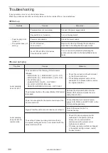
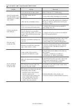
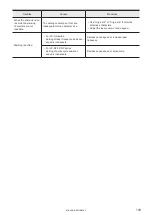
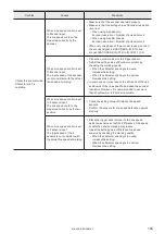
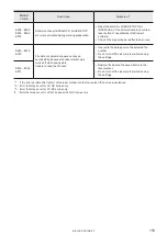
Troubles
Causes
Measures
The marking around
edge of the marking field
is faded or chipped.
Decrease of the laser energy density in
the edge of marking field may affect the
marking quality.
• For LP-GS/LP-RC series:
Set “Power optimization by marking position”
in “System offset” in System settings screen.
• For LP-RF/LP-RV series:
Set the power correction to the marking
objects in the edge of the marking field.
Character is partially
chipped.
Obstacle hinders laser beam.
Remove obstacle between laser emission port
and work piece.
Laser emission port is not clean.
• Clean contaminants off the laser emission
port by following the procedures described in
Setup/Maintenance Guide.
• For LP-RF/LP-RV series:
If contaminants persist, replace the protection
glass of the laser emission port.
Marking is disorder
(Characters lose shape
or not formed.)
Head lacks fixation strength.
• Fix head with the specified torque.
• Improve strength of head mounting.
Constant vibration from surrounding
equipment (motor and press, etc.)
influences.
Perform vibration prevention measures.
There are irregular vibrations coming
from surrounding equipment (air
cylinder and forklift, etc.).
(Marking is disturbed at irregular
intervals.)
Start and/or stop timing of feeder does
not match with marking operation.
Disturbed at the beginning of marking:
Marking trigger signal is likely to be input
before work piece is fully stopped. Marking may
disturbed due to remaining vibration even if work
piece is in full stop.Turn the marking trigger signal
ON after vibrations are completely damped.
Disturbed at the end of marking:
Work piece is likely to start moving before
completion of marking.
Delay start timing of feeder or speed up scan
speed so that marking is finished before work
piece starts moving.
There are noises coming from
surrounding equipment.
Protect laser marker against noises as follows:
• Securely ground the frame ground terminal of
laser marker or surrounding equipment.
• Isolate power and signal lines from each other
if they have been routed in parallel.
• Shield signal line.
• Isolate power supply for laser marker from
other equipment.
• Use noise cut transformer to absorb noises
from power supply.
Marking line runs over
the intended start or end
points.
The setting in lasing quality parameters
does not match the other settings.
Adjustment the lasing quality parameters such as
starting point, ending point or wait value in laser
settings.
ME-LP-GS-SR-COMP-3
Summary of Contents for LP-GS Series
Page 11: ...1 Preparation of Command Control ME LP GS SR COMP 3...
Page 26: ...2 Communication Control Basics ME LP GS SR COMP 3...
Page 50: ...3 Data Format for Each Command ME LP GS SR COMP 3...
Page 136: ...136 MEMO ME LP GS SR COMP 3...
Page 137: ...Troubleshooting ME LP GS SR COMP 3...
Page 163: ...Character Code Table ME LP GS SR COMP 3...
Page 176: ...Index ME LP GS SR COMP 3...
Page 178: ...178 W Warning 154 ME LP GS SR COMP 3...
Page 179: ......
Page 180: ...Panasonic Industrial Devices SUNX Co Ltd 2014 2019 April 2019...