


13
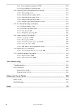
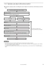
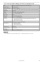
1-1-2 Operation procedure with external control
⿎
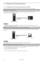
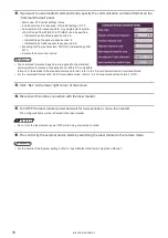
Operation example when controlling the laser marker from external control devices such as
PLC
Refer to “1-1-4 Remote mode settings” (P.17).
The device is ready for receiving the marking starting signal (trigger).
Turn ON key switch of laser marker controller
Marking
Control by serial communication
commands
I/O control
OPEN shutter
Remote mode ON
Select file
Confirm READY OUT is ON.
Trigger Input ON
Laser pumping ON
Control by using I/O or
communication commands
ンㄆㄇㄆㄓㄆㄏㄆ
• It is available to the external control combining I/O, and serial communication commands.
• You need to configure the system settings on the I/O communication in advance before using external control. Refer to
“1-1-3 Settings before external control” (P.14).
• For details on the operation procedure when you link an image checker or a code reader, refer to “Setup/Maintenance
Guide”.
ME-LP-GS-SR-COMP-3
Summary of Contents for LP-GS Series
Page 11: ...1 Preparation of Command Control ME LP GS SR COMP 3...
Page 26: ...2 Communication Control Basics ME LP GS SR COMP 3...
Page 50: ...3 Data Format for Each Command ME LP GS SR COMP 3...
Page 136: ...136 MEMO ME LP GS SR COMP 3...
Page 137: ...Troubleshooting ME LP GS SR COMP 3...
Page 163: ...Character Code Table ME LP GS SR COMP 3...
Page 176: ...Index ME LP GS SR COMP 3...
Page 178: ...178 W Warning 154 ME LP GS SR COMP 3...
Page 179: ......
Page 180: ...Panasonic Industrial Devices SUNX Co Ltd 2014 2019 April 2019...


