197
Message Delay Times
Section 9-4
Note Be sure to take into account the time required for data links and program exe-
cution, which are not included in the following example.
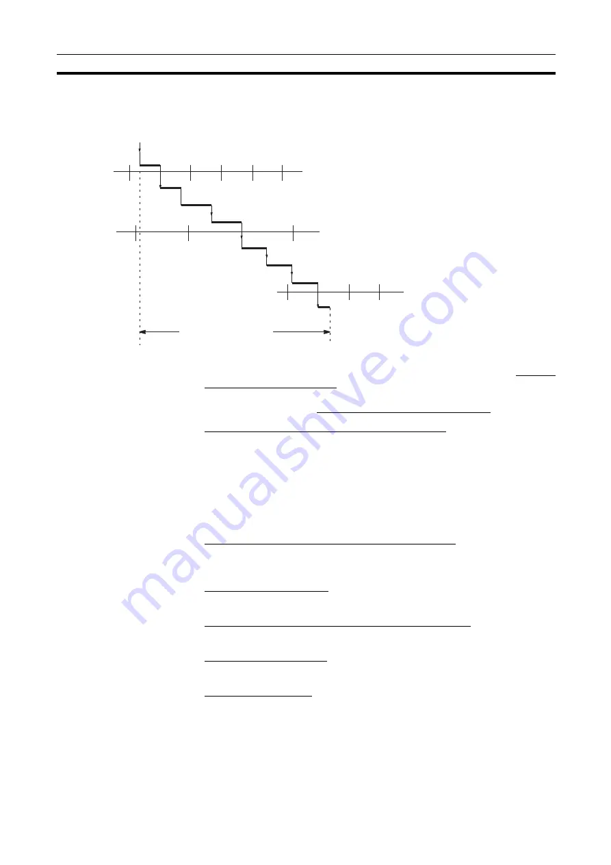
Max. transmission delay = Link Unit servicing interval (local node) + Link ser-
vice processing (local node) + Transmission proc Communications
cycle time + Transmission delay + Reception proc Link Unit servicing
interval (remote node) + Link service processing (remote node)
Link Servicing Interval (Local and Remote Nodes)
Link servicing depends on the execution mode of the PLC. The execution
modes on the local and remote modes need not be the same.
For synchronous execution, links are serviced once per PLC execution cycle.
For asynchronous execution, links are serviced according to the peripheral
servicing interval. Refer to the operation manual for the PLC for details. Refer
to the CVM1 and CV-series PLCs Operation Manual: Ladder Diagrams
(W202) or CS-series PLCs Programming Manual (W340) for details.
Link Service Processing (Local and Remote Nodes)
Link service processing is the same as the PLC’s peripheral servicing and is
approximately 1 ms for Controller Link Units.
Transmission Processing
Number of words transferred
×
0.00075 ms + 2 ms
Communications Cycle Time (with Data Links Inactive)
See 9-2 Communications Cycle Time (on page 187).
Transmission Delay Time
Number of words transferred
×
0.008 + 0.112 ms
Reception Processing
Number of words transferred
×
0.00075 + 1.3 ms
Note The I/O response time can increase due to noise or restrictions on the number
of frames that can be transmitted while data links are operating.
SEND executed
Link Unit servicing (source node)
Transmission processing
Communications cycle
Data stored
Reception processing
Max. transmission delay
Link Service processing (source node)
Link Service processing
(destination node)
Transmission delay
Link Service
processing
(source node)
Summary of Contents for CS1W-CLK12-V1
Page 3: ...iv ...
Page 5: ...vi ...
Page 9: ...x TABLE OF CONTENTS ...
Page 11: ...xii ...
Page 59: ...42 Component Names and Functions Section 3 1 Dimensions Unit mm ...
Page 62: ...45 Component Names and Functions Section 3 1 Dimensions Unit mm ...
Page 91: ...74 CVM1 and CV series Optical Ring Controller Link Units Section 4 2 ...
Page 108: ...91 Setting Data Links Section 5 2 Device Information Setting Data Link Tables ...
Page 125: ...108 Checking Data Link Status Section 5 4 ...
Page 181: ...164 Setting Routing Tables Section 7 4 ...
Page 199: ...182 Memory Areas Related to Duplex Operation Section 8 6 ...
Page 275: ...258 Handling Precautions Section 10 7 ...
Page 298: ...281 CS series Optical Bus Controller Link Units Appendix C Dimensions Unit mm 101 35 130 ...
Page 299: ...282 CS series Optical Bus Controller Link Units Appendix C ...


